Download
1 / 17
170 likes | 318 Vues
The Latest Status of the KAGRA Cryogenics. N. KIMURA A , D. CHEN B , T. KUME A , S. KOIKE A , Y. SAKAKIBARA B , T. SUZUKI A , C. TOKOKU B , K. YAMAMOTO B , M. OHASHI B , and K. KURODA B. A High Energy Accelerator Research Organization, KEK B ICRR, University of Tokyo,. Outline

E N D
The Latest Status of the KAGRA Cryogenics N. KIMURAA, D. CHEN B, T. KUME A, S. KOIKE A, Y. SAKAKIBARA B, T. SUZUKI A, C. TOKOKU B, K. YAMAMOTO B, M. OHASHI B, and K. KURODA B A High Energy Accelerator Research Organization, KEK B ICRR, University of Tokyo,
Outline • Over View of KAGRA Cryogenics • Actual Work Schedule • Performance Tests • Cryostat • 1/2 Dummy Payload • Prototype Duct Shield • ( Preliminary tests ) • Summary
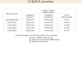
Location of Four Mirror Cryostats in Kamioka Mine Constructed at the position of 1 km in depth. Mozumi-End Atotsu-End X-Front Room Y-Front Room Mirror a cryostat Connection Port to SAS L=5 m Gate valve L=5 m Gate valve Vacuum duct800 with radiation shield Vacuum duct800 with radiation shield
Low vibration in U. H. Vacuum Stop propagation of 300K radiation Prevent heating by scattered beam Conceptual Design of the Cryogenics 80K PTC with Vibration reduction 4K PTC with Vibration reduction Baffles two units ~1W Cooling Cryo-Payload Main Beam 400kW 4W? • Four 4K cryocooler units per one cryostat • Baffles against wide scattering is cooled via 8K shield. 8K shield two units 300K Radiation 80K shield Duct Shield Cryostat Cooling 8K shield 2 units for cool cryo-payload 2 units cool for 8K shield 4 units cool for 80K shield
Overview of KAGRA Cryogenics Stainless steel t=20mm Diameter 2.4 m Height ~4.3 m M ~ 11 ton Cold Mass: 8K shield ~455 kg 80 K shield ~590 kg Seismic Attenuation System (SAS) Radiation Shields Cryogenic Payload 5 m Duct Shield Sapphire Mirror (-alumina crystal) 5 m Duct Shield Main Laser Beam Cryocoolers Pulse tube, 60Hz 0.9 W at 4K (2nd) 36 W at 50K (1st) Four Cryocooler Units S.Koike
Actual Work Schedule of KAGRA Cryogenics 2011 Jfy 2012 Jfy 2013 Jfy Apr./’11. Apr./’12 Apr./’13 Apr./’14 We are here 22th/Oct. Four Mirror Cryostats Manufacture components Design by KEK Assemble and factory test with cryo-coolers Transport to storage near Kamioka Bidding Cryo-cooler units Performance test Design by KEK Transport to Kamioka Production of seven cryo-cooler units with performance test Custody at Kamioka Production of nine cryo-cooler units with performance test Duct shield units Production of three ducts shield units without cryo-coolers Design by KEK
Cryo-payloadEsti. (W) Meas. (W) • Payload (~1.0?) - • Mirror Adsorption(~1.0?) - • Total (2.0 ?) - • W/unit (1.0 ?)0.4 Performance of the Cryostat • 8K Shield Esti. (W) Meas. (W) • View Ports (0.4)* - • Radiation From 80 K 2.2 - • Support post and Rods 2.4 - • Electrical wires 3 x 10⁻⁴ - • Duct Shields ( < 0.05 ?) - • Total 4.6 (5.0 ?)<2.0 • W/unit 2.3 (2.5 ?)<1.0 Performance test at Toshiba Keihin Product • It took 12.5 days to cool down from 300 K to 8K. • Cool down time of the cryostat was almost consistent with the predicted cooing time by Calculation model. • 80K Shield Est. (W) Meas. (W) • Eleven View Ports (22) - • Radiation From 300 K 70 - • Support post and Rods 24 - • Electrical wires 3 x 10⁻⁴ - • Total 94 (116)125 • W/unit 24 (29) 31
Cooling test in Toshiba Heat load Test Heater and thermometer Pulse tube cryocoolers Pulse tube cryocoolers Sapphire mirror Pulse tube cryocoolers 8 8 8 8 8
Cooling test in Toshiba Result of Heat Load Response @ Cryo-payload line 10 W 4 W 0 W According to our design, temperature should be below 8 K when heat absorption in mirror is 1 W. It is confirmed that 2.5 ppm (1 W) @400 kW of mirror deposition is acceptable as heat load for the cryocoolers connected with cryo-payload line. 9 9 9 9 9
Results (with copper heat links) • Cryo-coolers for payloads didn’t cool down completely (2nd stage stayed at 20 K) • Thermal conductivity of heat links calculated from results: 1/5 of literature • Thermal contact resistance between payloads and heat links Emissivity Sapphire: 0.5 Platform: 0.3*(T/300K) IM: 0.4*(T/300K) 2013.9.22 日本物理学会 2013年秋季大会 榊原裕介 Yusuke Sakakibara 10
Performance Test of the Prototype Duct Shield Measurement of thermal radiation Two aluminum plates suspended • 600 mm plate (Left side) is heated up to 300 K and emits thermal radiation • 250 mm plate (Right side) absorbs radiation and is heated up • Calibration is conducted using heater on 250 mm plate • Coated with Solblack to enhance emissivity or absorptivity Thermal Radiation 40 K 150 K 250 K 600 mm 250 mm 17 m Done by Y. Sakakibara
Results • Calculated value has error of several times • Measured reflectivity at 10 μm of shield has error • Rays are reflected by shield many times • Measured value is within the error Reduced by Duct Shield Reflectivity at 10 um Duct 0.94±0.02 Solblack 0.7±0.1
Measurement of scattered light • Red light from laser diode • Photographs of scattered light when angle changes • Calibration by changing exposure time • Future work: Vibration measurement, calculation of equivalent GW amplitude 635 nm, 4.5 mW ~200 ppm of laser light came back to camera Background Yusuke Sakakibara
Modal analysis for KAGRA Duct Shield Gravitational Direction 5m Φ800 Fixed points We analyzed the resonance peaks of the vacuum chamber without bellows and the inner shield. Mode frequency are calculated from 20 Hz to 100 Hz.
Shape of duct shield at each resonant frequency. Resonant Frequency F1 18.85 Hz F2 25.48 Hz F3 38.52 Hz F4 40.28 Hz F5 40.99 Hz F6 43.65 Hz F7 44.20 Hz F8 46.31 Hz F9 49.01 Hz F10 59.07 Hz F11 63.66 Hz F12 64.58 Hz F13 68.25 Hz F14 68.69 Hz F15 73.87 Hz F16 77.00 Hz F17 77.16 Hz F18 94.00 Hz F19 96.18 Hz F20 99.86 Hz F17 77.16 Hz F18 94.00 Hz F20 99.86 Hz F19 96.18 Hz It was confirmed that the most of resonant frequencies are cause of strength of the vacuum chamber, and weaker than that of inner shield. These results have been feedback to the duct shield design.
Structure view of the Production Duct Shield Baffles 80 K Duct Shield Bellows Support Frame Vacuum Vessel 5 m
Summary 1. KAGRA cryogenics consisting of cryostat and cryo- cooler units was designed, fabricated, and tested their performances during 2011JFY and 2012JFY. 2. At the performance test, following items were confirmed and verified; • The cooling and vibration performance of sixteen cryocooler units. • The cooling performance of all the four cryostats. • Vibration on the surface of inner radiation shield. • Experiment with half size of dummy cryo-payload 3. Experiment with proto type duct shield was conducted, and result was agreed with predicted heat load. But, need more analysis work. 4. Design of the production of duct shield were almost finished. Now, We are focusing our work on fabrication of the duct shields and preparing performance test.