Download
1 / 25
250 likes | 449 Vues
WD 13 / 15 Frame: The robust stabile frame is based on a skeletal design. This enables technicians unhindered access to the vehicles operational components and the battery. All covers are designed to be removed or open on hinges.

E N D
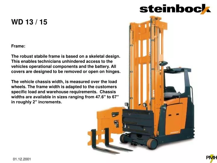
WD 13 / 15 Frame: The robust stabile frame is based on a skeletal design. This enables technicians unhindered access to the vehicles operational components and the battery. All covers are designed to be removed or open on hinges. The vehicle chassis width, is measured over the load wheels. The frame width is adapted to the customers specific load and warehouse requirements. Chassis widths are available in sizes ranging from 47.6” to 67” in roughly 2” increments.
Product development Production started with the Man Up - style WA 13 / 15 vehicle the end of 1997
WK 10 1998 Steinbock - introduced the WK model ~ ac drive order selectors in both initial lift (shown) & walk-thru versions. WK 15
Product Series NEW Next Project WM 13 WK 10 / 15 WD 13 / 15 WA 13 / 15
Benefits of Man Down vs. Man-Up • Increase productivity up to 25% with the use of the built in height selector & horizontal positioning (option) • Save up to 25% of energy consumption without raising the operator cab • Maneuverable and able to negotiate smaller intersecting aisles due to the elimination of the cab dimension • Fast operator adaptation to controls similar to standard conventional counterbalance forklift. • Operator comfort enhanced - elimination of constant up-down (elevator movement) and in the sommer even possible fatigue under hot roofs
2000 Introduction of the New WD 13/15 Design Concept • Symbiotic with front and side seat vehicles • Transfer of technology from the successful WA series • Interchangeable parts between WD & WA series vehicles • Vehicle to suit all existing WD customer sites or better
WD 13 WD - Series WD 15
WD 13 / 15 Wheels: The load wheels are mounted on independent load axles. The bearings are conical roller bearings that provide ease of maintenance and adjustments as well as very easy tire exchange when required. Load Wheels: WD 13 11.6 x 5.7” WD 15 15.0 x 6.0” or 15.0 x 7.6” depending on frame size Material: Tractotan Drive Wheel: WD 13 / 15 15.7 x 6.3” Material: Polyurethane
WD 13 / 15 Drive system: • Stationary high performance ~ ac drive motor with 7 kW (KB 60 min.) bolted directly on to the single wheel transmission. The ~ ac motor requires no maintenance (NO brushes) and has a very high torque rating. Steering: • An exceptionally smooth and responsive electrical steering system. The small operator steering wheel is incorporated into the pilot control center. When operating in rail guided mode, a push button sets the steered wheel to the straight position disabling the steering wheel input. The position of the steered wheel is indicated in the operators LCD display. The steering response ranges between +/- 90o making this 3 wheel vehicle exceptionally maneuverable in tight intersecting aisles.
Load Handling Attachment: • The standard vehicle is outfitted with a turret attachment. Loads can be placed or retrieved from floor locations. Loads directly in front / left or right side of the vehicle can be handled by this attachment in a narrow aisle configuration. • All end positions of the attachment (side shift or rotation) are automatically end dampened. Operators don’t have to worry about feathering the load - the equipment is programmed to do this task automatically. • For quick rotation of the load, the shift and rotation movement can be synchronized and coordinated for the specific load & aisle size. This option allows the operator to rotate the load in the narrow aisle with the touch of a button. • Optional telescopic load attachments are available to handle skid type or pallets without bottom boards – further reducing the normal working aisle (load + 8”) over the standard turret attachment (load + 16”). • The turret attachment may also be fitted with synchronous or asynchronous fork positioner.
Mast The mast selection covers 2-stage clear view or 3-stage full free lift models. Both are precision manufactured with double T profiles, cross braced with channels, the design provides torsion resistance and bend stability. These features are desirable to narrow aisle equipment in that in minimizes mast sway or lean during the load / unload cycle. The hydraulic cylinders are mounted on the outside of the mast profile enhancing the operators view. Design
Ergonomic Design Operators Compartment • The drivers seat, control panel and foot pedals rotate 30o in the load direction and 10o in the steer wheel direction - under operator control via toggle switch in a stepless manner. • The comfort seat is suspended and dampened against vibration. The seat is adjustable to the operators body weight and dimensions. The control panel and integrated arm rest are height and distance adaptable. • All functions for lift, lower, side shift and rotation are enabled via thumb
Ergonomic Design Height Selector • The integrated height selector mounted in the control panel of the pilots compartment allows the operator to select the load level via keyboard entry. When reaching the desired level the lift or lowering process is completed. The load / unload process is also controlled by the height selector pending operator initiation at the desired horizontal position. • The height selector is setup to control multiple zones with varying rack levels. The integrated system infinitely controls lift / lower velocity based on a programmable ramp slope to user defined end fork position, maximizing operator productivity.
Ergonomic Design Operator Console • The spacious physiologically designed work environment includes comfort seat and optimized positions for all the control elements. The results furnish the operator with a sense of unparalleled handling & control which further reduce operator fatigue and stress over long periods of operation. • Control. Operational conditions are displayed on the LCD such as: Lift Height, Battery Discharge Indication, Time, Position of Steer Wheel, etc …
Ergonomic Design Integrated Height Selector with Load / Unload cycle Keypad Input Battery WD 13 36-125-9 (72 volt, 500 Ah) 42.2 x 22.9 x 34.6 compartment WD 15 36-125-13 (72 volt, 750 Ah) 42.2 x 34.2 x 34.6 compartment Battery compartment is suitable for a single tray battery but may be divided to handle (2) 36 volt batteries instead. Battery rollers and hinged cover with removable sides are provided to offer ease of use - daily battery check or maintenance. The battery discharge indicator and hour meter are part of the overall controls displayed on the operators LCD screen.
Productivity / Safety Height Selector and horizontal positioning aids • Integrated Height Selector with automatic load / unload cycle • Horizontal positioning with aid of laser pointer located on mast and pointing to floor or rack markers. • Help the operator position fork accurately and quickly.
CAN-BUS CAN-Bus and continuous measurement sensors make end switches and adjustments obsolete. 60% less cable and wiring over conventional vehicles. Control of all sensors based on priority protocol maximizes operational safety. Automatic dampening set on all hydraulic end movements, as well as the mast transition between stages. The technology is also commonly found in the automotive & heavy equipment industry in harsh environmental settings. ~ ac, Energy Control and CAN - Bus Safety Motor Control Control Panel Steering & Wire Guidance Load Attachment
Productivity Comparison of work cycles • Aisle 60 m = 196‘ • Top level 12 m = 39‘ • Battery 750 Ah • Calculation basis 50 % • Distribution 30 % 37 25 % 32 % 7 % 30 28 Higher productivity with New WD potential savings of an additional vehicle to the customer
Productivity Comparison - max. number of workcycles with 750 Ah Battery 278 • Aisle length 60 m = 196‘ • Top Shelf 12 m = 39‘ • Calculation basis 50 % 20 % 25 % -5% 236 223 Smaller battery requirements for WD reduced capitol investment
Parameter Control Management (PCM) - Laptop Service Diagnostics • Diagnoses: Maintenance and trouble shooting via laptop and our JustControl diagnostic software. • Remote Diagnoses: possible via cell modem or laptop PC modem to one of our service centers or direct to the factory. When connected via laptop and modem – training is provided in real time mode. Local service technicians are able to follow along step by step on the computer screen – as they watch and assist the factory technician manipulate and control the vehicle.
Service and Safety • Motor Control System • The decentralized control system, on the ~ ac powered forklift vehicles, provides jerk free - - smooth powerful acceleration in every movement. The longevity of the equipment is ensured by the minimal heat buildup and wear free component design. • Best possible component accessibility even within the narrow aisle 80 % identical components with the WA - Series
Performance Rated • Standard Equipment • Battery Discharge Indicator • Hour meter • Steer Wheel Centering via button • Diagonal Travel with optimized acceleration profile based on direction of direction • Rotating operators compartment w. adjustable control panel • Electric servo controlled steering • Pin-point Position indicator for horizontal positioning • ~ AC drive motor technology • Height dependant brake force application • Mirror on left / right of mast • Turret attachment SX • Speed regulation and end dampening of all hydraulic movements • MOSFET electronic drive control with regenerative braking • Energy recovery while lowering • Vehicle controls with CAN-Bus technology • Suitable for single tray battery located on rollers • Error display with memory • Aisle detection for guide rail application • Steering Wheel position display • Height Selector QualityTested • 50.000 Lift / Lower movements (max. Lift) with capacity rated load • 150.000 shif t- and rotation - movments of the attachment • 100.000 Seat rotations with 175 lb. load • 320.000 brake applications on test track • Component testing equal to over 4000 hours of hard working environment
Options WD 13 / 15 Special Equipment • Overhead guard mounted fan • Work light mounted to overhead guard • Work light mounted to the turret attachment • Operator compartment lighting • Stereo – auto radio / cassette with 2 speakers • Mounted Clip board • Wire Mesh on Overhead guard • Macrolon shield on Overhead guard • Turret Attachment in special dimensions or additions • Standard Telescopic Forks • Low profile Telescopic Forks • Synchronous fork positioner • Side shift limitation and logic for (2) different pallet insertion dimensions • Wire Guidance • Rail guided – additional guide rollers in front of load wheels • Special paint / colors • Interface for data communications systems • Static roller on guide rail • Speed restriction with / without stop at the end of the aisle • Lift cut out / Drive cut off based on zones • Additional Power Supply for peripheral equipment • Rotating beacon • Split battery compartment with rollers • Battery Carts • Battery Charger mounted to mast for power rail applications • Automatic fork centering • Personnel detection via laser scanner integrated • Enclosed operators cabin • Special forks • Rack location load sensing / for height selector automatic load / unload mode • Horizontal positioning – automatic • Driverless vehicle
WD 13 / 15 Brakes a) The vehicle can be brought to a halt by releasing the accelerator or by changing the travel direction – turning the drive motor into a motor brake generator. This normal method of braking does NOT use the vehicle brakes providing wear free braking. b) More remotely the vehicle can be stopped via hydraulically activated expanding shoe brakes located in the load wheels. A standard brake pedal is provided for the operator. The maximum brake retardation is automatically dynamically set, depending on the lift height of the forks (or load) while traveling inside or outside of the working aisle. This eliminates to a high degree any operator error during the braking process, maintaining the maximum stability for the vehicle. c) The electromagnetic motor disc brake acts as a holding brake during the load / unload process and also as a parking brake when the vehicle is turned off. This brake is also applied during an E-stop condition. d) All wire guided vehicles are also provided with a solenoid activated hydraulic brake system. The release during an E-stop condition acts on the front load wheel brake shoes. The brake pressure is regulated depending on the lift height of the forks (or load) while traveling in the working aisle.
WD 13 / 15 Hydraulic • All hydraulic movement is provided by the ~ ac 21 kW pump motor coupled to a very quiet gear tooth pump. The hydraulic oil distribution is controlled via micro magnetic valve blocks. The volume of oil is a function of the control system that controls the rpm of the motor rather then bypass fluid via a spool or proportional valve. Only the amount of oil required to operate the function is provided. While lowering the pump motor is turned into a generator. The energy created is returned to the battery.