Download
1 / 46
480 likes | 629 Vues
ASICs for high temperatures and harsh environments. IRTG, Bergen 17 October 2012 SINTEF ICT Joar Martin Østby Senior Research Scientist joar.m.ostby@sintef.no joar@ifi.uio.no. Outline. Definitions ICs in general High temperature in general Market Challenges

E N D
ASICs for high temperatures and harsh environments IRTG, Bergen 17 October 2012 SINTEF ICT Joar Martin Østby Senior Research Scientist joar.m.ostby@sintef.no joar@ifi.uio.no
Outline • Definitions • ICs in general • High temperature in general • Market • Challenges • Substrate, connectivity and integration • Semiconductor technologies • Integrated circuits (ASICs) • Discrete components: sensors and devices • Standard components • Activity at SINTEF • ASICs • Harsh environment projects
1. Definitions Temperature range • Standard/commercial temperature range: 0°C-70°C • Industrial: 0°C-85°C • Military temperature range: -40°C-125°C • High temperature (HT): > 125°C • Very high temperature > 250°C • Low temperature (LT) < -40°C • Very low temperature < -150°C • Extremely low temperature < 40°K • HTE: High Temperature Electronics
Electronic operational range • Total reported temperature range: -270°C - 700°C • Lower end (-270°C): Si, Ge, GaAs • Higher end (700°C): Diamond Schottky Diode, SiC MOSFET (650°C), Si and GaAs ICs (400-500°C). • Operational range of same component: -270°C to 400°C
What are the benefits of ICs? • Small size • Less parts • Simple logistics • Low weight • Higher frequencies/clock rates • Increased reliability • Easier to protect in harsh environments • Low power consumption (energy consumption and heat) • Less noise sensitivity to most types of noise • Less noise emission • Lower price in medium and higher volumes • Improved performance/price ratio • Better hiding of design solutions • Better total system performance • Increased flexibility (some functions can only be implemented in ASICs)
Market is increasing but will continue to be a niche market • Large majority of HT applications in the range 125°C-200°C • Main customers: • Automotive • Avionics/Space • Oil & Gas
Oil & Gas – Operating conditions • Well depths: • Oil and gas: 3-6 km • Geothermal: 10km • Temperature range: • Majority of oil wells are under 125°C with 80% < 150°C • Only 2-3% are > 200°C • Geothermal wells: 25°C to 400°C with most wells covered by 325°C
Requirements for in-well systems • Passive and active electronics • Reliability is # 1 (more important than cost) • Application areas • Permanent in-well monitoring • <200°C with years of continuous operation • Well logging systems (wireline operation) • <220°C with operation for some few days • Drilling • <220°C with operation for 2-3 months • Geothermal and steam assisted wells • > 300°C operation and years of operation
Oil & Gas – Environment conditions • High temperature • Low temperature • Thermal cycling • Moisture • Hermeticity • Residual stresses • Vibration • Shock • Thermo mechanical effects • Ionising radiation • Aggressive chemical environments
Physical temperature dependencies … Fermi level Intrinsic carrier density Carrier generation rate Carrier mobility … is resulting in a change of … Conductance Transconductance Leakage current Diode voltage drop FET threshold voltage HT influence on silicon devices
Reliability Electro migration of conductors increases Chemical reactivity increases Diffusion of dopants and ohmic contacts increases Dielectric breakdown strength decreases Mechanical stresses increases Latch-up HT influence on silicon devices
Semiconductors Small Die with High Pad Count and/or High Power Density – Improved current density capabilities and higher operating temperature
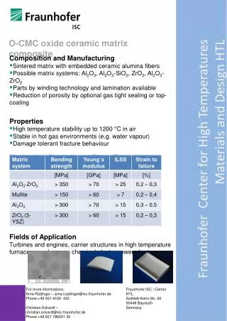
Core NMOS, PMOS, R and C 3 metal layers 90V drain-source voltage 5V gain-source Optional Metal Al 175°C Tungsten 225°C High res poly Cap (90V) 0.13fF/µm² (1cm² ~ 13nF) 1µm oxide layer 650µm handle wafer Reduced Cpara reduced Pdyn Reduced Ileak reduced Pstat X-FAB XI10 SOI-process
HT (200°C) and HV (600-800V) devices • UnitedSic • 4H-SiC BJT(150°C, 600V), VJFET (200°C, 1200V) and Shottky Diode (700V) • TranSIC (225°C 800V) • SiC BJT, Si IGBT • BitCsic • SiC NPN power (250°, 1200V)
-50°C to +200°C 16-bit TMS320F240 DSP core 16kw flash & 32kw SRAM Inte. RC osc 2.304MHz±1% 8 10-bit ADCs, 10µs 3 10-bit DACs PWM outputs Applications Petroleum Aircraft Smart sensor applications TX530: DSP, ADC’s, DAC’s, Dig I/O
µPEK activity • Interconnects • Wire bonding, die-attach, micro bumps (3D stacking) • Components • Thick and thin film resistors • Ceramic capacitors • Microcontroller • Diode laser • Optical transmitter and receiver
µPEK: ATMega88 Microcontroller • The Atmel ATmega88 selected because: • Popular, modern 8-bit architecture. • Low power consumption. • Automotive version available, specified to +125°C (+150°C). • A lot of different variants, made in the same process. • Internal EEPROM and self-programmable FLASH. • Wide operating voltage range, 2.7 – 5.5V @ -55 – +125 (+150)°C.
µPEK: Results ATMega 88 • Operation limit around 180C. Latch-up observed at 185C • One component have survived 8 months operation at 180C without any signs of degradation. • Further testing of a number of components in parallel is required.
Substrate metallization Resistors Wire bonding Capacitors?? Die attach Integrated circuits µPEK: 7 years operation at 200C. Is it feasible? Use small capacitance values Derating is highly important! Use Class I (NP0) capacitors
High Temperature Instrumentation for Oil Production • Temperatures: 0 - 200 ºC • Pressure: 0 - 1000 bar • Vibration, shock • Aggressive liquids/gases • Difficult/expensive to test Environmental characteristics:
High Temperature (~200°C) at SINTEF TOPSIDE UNIT • Started 1984, design of logging tool • Characterisation of CMOS/BICMOS technology for HT in 1988 • First ASIC in 1992. Complex mixed signal circuit working up to 275°C • Almost all work related to tools for the petroleum sector Power Data transfer card Rx/Tx 4km 1/4" downhole cable 13W/km,100nF/km DOWNHOLE CONTROL MODULE Communication Sensor#1 Sensors unit #2 - #6 P ELS-001 TMM TTC T TTC HTPOWER HTPOWER single conductor local bus inside tool string Up to 6 control modules may be connected in series (2 x 1/8" downhole cable) Signal and power bus
Library of high temperature ASICs • TMM Telemetry Master Module (long distance biphase telemetry Tx/Rx, system sync) • TTC Telemetry Tool Chip (time multiplexing, directly connected to single wire bus) • HTP High Temperature Power (serial regulator with built in reference voltage) • ELS Quartz oscillator control chip (four channel oscillator/mixer for quartz sensor interface) • CMC Capacitance Measurement Circuit (capacitance measurement, pF-nF, <1%, high res.) • S/D A/D converter based on sigma-delta principle (A/D-converter diff. input +-1V, < 0.1%, low noise) • VFC Voltage to frequency converter • SAC Spectrum Analyser Chip (not yet fully verified) (spectrum analyzer chip 500Hz-50kHz) The chips are designed for use at temperatures up to 200°C. They may either be put together as a complete system for remote measurements or be used separately. TOPSIDE UNIT Power Data transfer card Rx/Tx 4km 1/4" downhole cable 13W/km,100nF/km DOWNHOLE CONTROL MODULE Communication Sensor#1 Sensors unit #2 - #6 P ELS-001 TMM TTC T TTC HTPOWER HTPOWER single conductor local bus inside tool string Up to 6 control modules may be connected in series (2 x 1/8" downhole cable) Signal and power bus
NCM-eye • Goal: Measure resistance in rock • Two ASICs designed for 200°C operation temperature • Measurement setup: • 100-200V AC is set up over the rock region to be inspected • Sensor front ends width very high input impedance (10-100G) measure the local voltage level • Voltage differences between neighbour pairs are found • Resulting values are converted into a digital format and feed into common buses
PharusITPhased Array Ultrasonic Transducers for Inspection of Tubing • EU project partners: SINTEF (Norway), Schlumberger - Ribound Product Center (France), Schlumberger - Doll Research (USA), CSIC (Spain), IMASONIC (France), TRONICO (France), STATICE (France) and BAM (Germany). • The primary objective of this ultrasonic imaging system was to perform non destructive testing in fluid filled oil wells. Typical specifications are 1400 bar and 175°C in harsh environments. • A variety of tasks are performed by the same system. E.g. locate rock fractures in the borehole wall or assess the quality of the cement placed in the annular space between cased steel pipe and rock wall. • The system architecture consists of a 2-D transducer array of 800 elements, a transmitter block, integrated front end receiver electronics, and FPGA circuits for controlling the array elements and performing the digital beam forming. • Publications and presentations: • HITEN 2005 • ESSCIRC 2005 • IEEE International Ultrasonic Symposium 2005. • IEEE Journal of Solid-State Circuits 2006
The library of complex circuits We have today a library of working circuits that we sell. Several of them have a rather general behaviour and could be used in different systems. These are rather complex circuits containing several thousand transistor equivalents each. New ASICs We sell our high temperature design competence and design new circuits according to specifications by the customer. Simple standard cells We may design and sell simpler "standard" cells. This may be a possibility for one customer or for several customers co-operating for the same specification. Possible circuits may be amplifiers, switches, memories etc. Synthesized layout from customer input We may generate digital layouts with our high temperature digital library from specifications given by the customer. The specification may be in some kind of high level language. Examples here are micro controllers delivered by the customers or from our contacts. High-temperature CMOS services
SINTEF ICT, Dept. for Instrumentation • Main focus is Instrumentation for demanding environments • Enabling technologies Micro-, opto- and nano-technologies are used to develop innovative integrated products and sensor systems in close collaboration with • Industrial partners • Start-up and venture companies • Applications areas • offshore, subsea, oil- and gas wells • process industry • automotive • Health related ICT • Lean technology approach
Centrifugal Separator Level Gauge (2000) • 3600 rpm • Capacitive level detection: - 0.1mm water/oil, - 0.3mm gas/oil • Non-contact signal transmission • Built-in power generation • Operation at 0-100 ºC,3600 g acceleration • Operated successfully for >2 years
SLG (Separator Level Gauge) • Measure pressure at several vertically separated points in the separator tank and combining the results mathematically to extract the water/oil/gas levels. • Measuring these small levels of change in pressure (<100pa) is achieved by using differential pressure sensors arranged in an vertical array. • The instrument has been tested for line pressure up to 196 bar and temperature up to 125°C Celsius. • Patented by Statoil • Pressure certified by DNV (Det Norske Veritas Certification AS) • EX certified by Nemko • Planned to be installed at Oseberg
Noise Recording tool (Acoustic logging tool) Main specifications Sensor element (patent pending) FFT Plot
Ongoing and future projects • Wireless in-well communication systems (semi-permanent – commercial phase) • In-well acoustic noise recording tool (wireline – commercial phase) • High reliability in-well instrumentation platform for the future (SINTEF strategic project - research) • Pipeline monitoring for integrity and corrosion control (permanent – subsea pilot phase) • In-well timer and release with very high accuracy (Research and test phase – permanent) • ++