Download
1 / 43
430 likes | 820 Vues
Exotic Antenna Pattern Measurements. Greg Ordy, W8WWV ordy@seed-solutions.com 2010 Dayton Hamvention Antenna Forum. Overview. NEC-Based Antenna Modeling is an indispensable part of antenna design. But… I’ve never made a single contact on a model!

E N D
Exotic Antenna Pattern Measurements Greg Ordy, W8WWV ordy@seed-solutions.com 2010 Dayton Hamvention Antenna Forum
Overview • NEC-Based Antenna Modeling is an indispensable part of antenna design. • But… I’ve never made a single contact on a model! • No lack of confidence in NEC, but rather a lack of confidence in my ability to model (antenna and environment), and then implement the model. • Trust but verify (the more I can measure, the better I sleep). Exotic Antenna Pattern Measurements
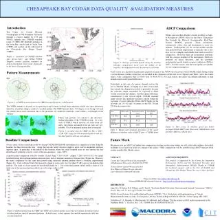
Two Years Ago on this very Spot… • At the Antenna Forum in 2008 I presented some work on measuring complex antenna currents on phased arrays using a VNA, a little custom hardware, and some custom software. • Measured currents were inserted back into models to create gain and pattern predictions, across the whole band, not just 1 frequency. • I wanted to cross check my results, especially when they seemed a little strange. Exotic Antenna Pattern Measurements
Two Years Ago… • Consider my 6-element 80 meter phased vertical array, targeted for the SSB DX window. • Due to the use of trapped elements (for 2 band operation) and compromise spacing (40’), I always expected a small performance bandwidth on 80 m. • Initially, I was happy to hit my target currents at the single design frequency, but that’s one frequency. • Because I had an 80 m Inverted Vee several hundred feet away, located on a major axis, I realized that I could measure the F/B ratio using both antennas and two VNA transmission measurement sweeps. Exotic Antenna Pattern Measurements
Two Years Ago (2)… • Sweep the transmission response in one direction, then the other, transfer to an Excel spreadsheet, subtract back from front to produce the F/B ratio, graph the result. Exotic Antenna Pattern Measurements
Two Years Ago (3)… • Similar results using two different approaches – cross checking. Exotic Antenna Pattern Measurements
Two Years Ago (4) • Measurement of the F/B ratio using my home antenna test range was fast and easy, but it was a lucky accident to have a second antenna close to the desired alignment, and preexisting transmission lines coming to a central point. • I wanted to generalize the measurement approach, and use it in other situations. This presentation describes what happened next… Exotic Antenna Pattern Measurements
Let’s Get Through the Theory… • What are the factors controlling the signal level between the transmitter and receiver? • Transmit Power Level • Cable Losses • DUT Antenna Response (AUT) • Path/Propagation Characteristics • Secondary Antenna Response • Receiver Settings (attenuator/preamp/detector calibration) • All we care about, and what we want to isolate, is the AUT response. • We can do that by trapping the desired AUT characteristic between two measurements that are then subtracted. • So long as everythingbut the AUT response is held constant, the AUT characteristic is all that remains. Exotic Antenna Pattern Measurements
Theory (2) • It is obviously essential that all conditions (S) other than the AUT response be held constant across measurements. • If not, their difference will show up in the final result. • This is not a true F/B measurement, since it’s comparing one directions front to another's back (unless we rotate). • We are making signal strength transmission measurements, and ignoring the phase response. Exotic Antenna Pattern Measurements
What Can We Measure? • Most anything that can be captured as a pair of subtracted measurements. • F/B Ratio: Perhaps the most obvious. • Gain: By comparing against a reference, such as the gain of a single element in the array. • Side to Side Ratio: Helps detect pattern distortion/symmetry. Exotic Antenna Pattern Measurements
Antenna Test Range • We are talking about creating a traditional Antenna Test Range environment around our backyard antennas. • Much has been written on this topic, many good references. • The #1 requirement is to be able to test in the far field, beyond the Fraunhofer distance (d = 2D²/). Other rules of thumb suggest 3 to 10 separation (minimum). • For the HF bands, the distance between the AUT (Antenna Under Test) and the secondary antenna needs to be several hundred to several thousand feet. • This means that we need to be able to operate and synchronize a transmitter and receiver connected to the two antennas within a few miles of each other. Exotic Antenna Pattern Measurements
Antenna Test Range (2) • Given the distance, we aren’t going to be able to run cables between the antennas, so we will need two separate synchronized and calibrated stations. • Each station consists of a radio, control computer and antenna. • Two relatively close stations, or one fixed and one mobile station. • How do we synchronize the stations? • Being a computer geek, a wireless Internet scheme was considered, but in the end, a simple trigger and sweep scheme has worked well. Exotic Antenna Pattern Measurements
The Software • A single program (Soil) is used on both sides (transmit and receive) of the measurement. • The program controls a radio transceiver. • Needed capabilities are minimal – CW transmit, change frequency, read S Meter. • Currently works with ICOM radios, but is built upon an extensible device driver model. • Based upon S Meter calibration across a 60 dB range. Given the typical distances and signal levels, 0 dB is mapped close to +40 to +50 over S9 on the S Meter. Exotic Antenna Pattern Measurements
S Meter Calibration • S Meters are usually poorly calibrated on the meter, but if you can read the meter over the computer interface, you can create your own calibration curve. • Creating a 60 dB range with 1 dB accuracy is not difficult. • Use an RF Generator and calibrated step attenuator for setup. My IC-706MKIIG Calibration Curve Exotic Antenna Pattern Measurements
Sweep Description • Each radio must follow the same frequency list. • The list specification has 3 parts. • Spot Frequency (optional) (for setting signal levels). • Primary Start/Stop/Step. • Secondary Start/Stop/Step (optional) (region of higher detail). Exotic Antenna Pattern Measurements
Timing and Control • Each station sits idle until the sweep is started on the transmitter computer by the operator. • The receiver computer constantly reads the S Meter and detects the first signal that exceeds the signal threshold. That starts the receiver cycle. With 1 sec. Period and 40 CPS, ~8 samples are averaged to make one reading. A whole band can be swept in around a minute (60 points). Exotic Antenna Pattern Measurements
Transmitter Perspective • The XMIT button turns on the transmitter for setting signal levels. • Start begins the sweep. • Timing errors show deviations from the high resolution CPU counter, which is very accurate in the short term. Exotic Antenna Pattern Measurements
Receiver Perspective Exotic Antenna Pattern Measurements
Analysis Perspective Exotic Antenna Pattern Measurements
Pitfalls and Potential Problems • Many. For example, probably not appropriate for NVIS. • QSB/QRN/QRM. Best done on a dead band with no QSB. • Groundwave rather than Skywave signals. Ground clutter. Better to be located higher than the AUT rather than lower. • Develop Expectations from Models (understand Groundwave/low angle behavior). • Signal Overflow/Underflow. • Antenna Alignment Errors. Exotic Antenna Pattern Measurements
Groundwave Characteristics • The antenna behavior may shift at groundwave elevations. Modeling can help reveal what to expect. • Consider how the F/B might change as a function of take-off angle. • Lower angle, higher F/B in this example. Exotic Antenna Pattern Measurements
Groundwave Characteristics (2) • The frequency of the F/B peak may even shift as function of take-off angle. • This is a 40m 2-EL array with a cardioid pattern. As the take-off angle drops the F/B peak freq. drops too. Exotic Antenna Pattern Measurements
Antenna Alignment • Use a decent Compass (<= 1° accuracy) and GPS. I learned my array was off by 6°. Be sure to factor in declination. Exotic Antenna Pattern Measurements
Minimal Mobile Requirements It’s a joke. Apologies to the owner.. Exotic Antenna Pattern Measurements
Radio/Computer Mobile Test Stack Exotic Antenna Pattern Measurements
Results: 160 m K3LR Array • Described in 4th edition of ON4UN’s LowBand DXing. • Driven ¼ center element surrounded by 4 parasitic T elements, tuned as either open, director, or reflector. • 3-El end-fire array in 4 directions, plus omni mode. Exotic Antenna Pattern Measurements
160 m K3LR Array: Gain from NEC • NEC Model Results at 19° and 1° take-off angles • ~5 dB gain over omni, roll off on ends. Exotic Antenna Pattern Measurements
160 m K3LR Array: Gain from Measurement • Measured array and omni, with secondary antenna response and comparison. Exotic Antenna Pattern Measurements
160 m K3LR Array: Gain from Measurement (2) • Closer look at the measured array gain over the omni gain. Exotic Antenna Pattern Measurements
160 m K3LR Array: F/B • 1 and 19° F/B are virtually identical. • Not really pure F/B. • LBDXView – ON4UN 5th edition. Exotic Antenna Pattern Measurements
160 m K3LR Array: Side to Side • Useful to check for pattern distortion. Sensitive to azimuth alignment. Exotic Antenna Pattern Measurements
K8AZ 40 m Yagi’s • 3 different 40 meter Yagi’s • 4L @ 130’ • 2L @ 70’ • 2L @ 65’ (fixed 140) • I used my 20 meter Yagi (@ 60’) as a secondary antenna. Exotic Antenna Pattern Measurements
K8AZ 40 m Yagi’s (2) • 4L F/B Measurement: Exotic Antenna Pattern Measurements
K8AZ 40 m Yagi’s (3) • 2L “House” F/B Measurement: Exotic Antenna Pattern Measurements
K8AZ 40 m Yagi’s (4) • 4L Versus 2L Gain Comparison: Exotic Antenna Pattern Measurements
Power Attenuator Pads • Spill power for Receive or Transmit to help set signal levels. • Protect Transmitter from large SWR swings on small antennas (such as mobile). • Values such as 3, 6, and 10 dB are usually useful. Exotic Antenna Pattern Measurements
Power Attenuator Pads (2) • Formulas and Calculators all over the place (books & Internet). • PI and TEE designs – select based upon hunting results for non-inductive power resistors. • Good brush up on Ohm’s Law and resistor networks. Exotic Antenna Pattern Measurements
Power Attenuator Pads (3) • Use Open and Short on output to quickly characterize SWR limiting. • More attenuation = more limiting = more dissipation. w/Open: Z = 83.5, SWR = 1.67 w/Short: Z = 29.8, SWR = 1.67 (6 dB pad) Exotic Antenna Pattern Measurements
Power Attenuator Pads (80m) Exotic Antenna Pattern Measurements
Power Attenuator Pads (80m) Exotic Antenna Pattern Measurements
Power Attenuator Pads (160m) Exotic Antenna Pattern Measurements
Power Attenuator Pads (160m) Exotic Antenna Pattern Measurements
Conclusion • Another tool for the kit. Never enough checking and cross checking. • Takes some time to set up, but once you are measuring, large amounts of data are quickly collected. • Don’t kill yourself (especially when mobile). • Don’t cause QRM, dead bands are good for stable measurements and reducing QRM. • Please contact me if you are interested in the software. • Thanks to K3LR and K8AZ for their help and time. Exotic Antenna Pattern Measurements