Download
1 / 43
460 likes | 635 Vues
S.H.A.R.P. S lender H ypervelocity A erothermodynamic R esearch P robe. SHARP genesis. development of new UHTC’s, ultra high temperature ceramics shingles on shuttle max temp- 3000 F new UHTC max temp- 5000 F result- sharp leading edge profiles are now possible. SHARP profile.

E N D
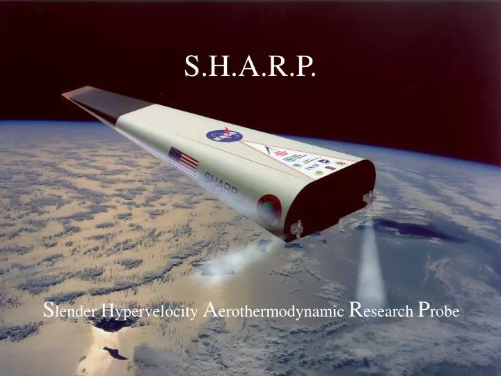
S.H.A.R.P. Slender Hypervelocity Aerothermodynamic Research Probe
SHARP genesis • development of new UHTC’s, ultra high temperature ceramics • shingles on shuttle • max temp- 3000 F • new UHTC • max temp- 5000 F • result- sharp leading edge profiles are now possible
SHARP profile • advantages • more efficient atmospheric exit and re-entry • better cross-range capability • (wider range of re-entry angles) • minimized radio blackout during re-entry • disadvantages • generates extremely high temperature at the sharp edge/tip
SHARP future • Next generation space shuttles- X-33 • nosecones • re-entry vehicles • launch vehicles (rockets & boosters)
SHARP PROJECTS • B-series • sharp nosecones • B1 re-entry vehicle already launched (B2 near launch) • S-series • university & small business partnership • test a knife edge geometry • 4 launches • L-series • full size • 2 launches • UHTC test
SHARP S-series • Atmospheric re-entry vehicles with knife edge profiles • reaches Mach 3.5 • UHTC not required • prototype sounding rocket launch vehicle • halfway to near earth orbit S4
S1 launch schedule • Orion class rocket launches • 4,000 lb thrust, 5g vibrations • S1 deploys at apogee • 270,000 ft • data acquisition begins • fin-tube stabilizer jettisoned • 150,000 ft • primary data capture • temperature, pressure, accelerations • S1 re-enters atmosphere • S1 parachute deployed • 20,000 ft • rocket and S1 recovery via helicopter
SHARP S-series goals • Create working relationships between NASA, universities and small businesses • gather aero & thermodynamic data on the SHARP-S profile • compare with computer simulations • Provide data for the L-series • S-series serve as prototypes • same geometry, ~ 2x size • UHTC equipped (mach 20 vs. 3.5)
SHARP S-series GROUPS NASA Ames Research Center project co-ordinator, aero/thermodynamics Montana State University re-entry vehicle structure Stanford University re-entry vehicle avionics Wickman Spacecraft & Propulsion launch vehicle & site
MSU SHARP TEAM PI: Dr. Doug Cairns MSGC: Dr. Bill Hiscock manager: Aaron Sears consultant: Will Ritter students: Mike Hornemann Kevin Amende Cindy Heath Crystal Colliflower Dustin Cram
MSU research groups • Montana Space Grant Consortium • federally funded program which disperses grant money to space oriented projects • Composites Research Group • co-directors: Dr. Cairns, Dr. Mandell • material characterization, structures & manufacturing • wind energy, aerospace
NASA designated responsibilities • Design and build the S1-4 re-entry vehicles using composite materials • integrate the structure with: • avionics (Stanford) • sounding rocket (Wickman Spacecraft) • low operating budget • faster, better, cheaper motto • $ 50k/year budget
S1 shape • S1 dimensions supplied by NASA 17” 4.4” 39.5” 6.6” 11.3o
mold peripherals assembly 4 part design ProE design FEM analysis design manufacturing * all design, analysis and manufacturing performed in-house at MSU
S1 design constraints results - epoxy matrix - metal tip (aluminum/steel) -composite shell w solid tip - carbon/epoxy • Withstand high temperatures • 600 F in shell (one use) • 1000+ F at tip • lightweight • CG in front of center of pressure • smooth aerodynamic surface • withstand dynamic pressures of 10 psi with minor deflections • unlimited systems integrations • provide locations & mounting for • pressure and temperature sensors • avionics components
S1 design • 4 part design • shell • component mounting frame • parachute • tip • base • peripheral & equipment • shell mold • fin-tube
S1 design fin-tube shell (mounting frame internal) base plate sensor arrangement tip S1 with fin-tube drag stabilizer cutaway view of internal mounting frame (spar system)
shell design • Provides the aerodynamic surface and serves as a main structural member • only surface interruptions are 6, ~1/16” holes for pressure and temperature sensors • One piece • only joint along aero-surface at tip interface • pressure bladder manufactured • IM7/8552 carbon/epoxy laminate • ~ 0.10” thick
shell/spar structure • Integrates the component mounting frame into the vehicle structure • spar system is removable for unlimited avionics & systems integration spars
spar system • 2 axial, 3 lateral • carbon/epoxy plates • mechanically connected • guided in by L-rails bonded into shell • spars mechanically attach into L’s for unlimited systems integration • 4th lateral spar of aluminum • sensor board mount on left axial
structural design drivers • aerodynamic pressures • ~ 10 psi at Mach 3.5 • launch vibrations • as Orion class sounding rocket • 6-g random vibration • heat • 600 F at tip/shell interface • +1000 F at tip • component space allocation • forward CG required advanced placement of heaviest components • governed possible placements of spars
hypersonic pressure analysis (inches) (02/±45/903)s hoop = 90, axial = 0, E1 = 20 Msi (~65% Vf, 0.058 lbf/ft3), t = 0.09” hypersonic skin pressure = 2.78 psi (Mach 3.5, 85,000 ft)
natural frequency analysis mode 1: 56 hz mode 2: 111 hz mode 3 : 180 hz (02/±45/903)s hoop = 90, axial = 0, E1 = 20 Msi (~65% Vf, 0.058 lbf/ft3), t = 0.09” (base plate constrained boundary condition)
tip & interface • design drivers • forward the CG location for aerodynamic stability • temperature resistance • pull-off (drag difference) force • smooth external interface • features • aluminum • better machining control • 1/2” lip for shell overhang • improves transition and connection • steel parachute line mounts • better impact/fracture properties than composites
tip interface sketch mounting bolt steel mounting plate tip link parachute line lip retention cup epoxy shell epoxy gap sanded flush
S1 sensor locations Pressure (8) Temperature (4) • The
parachute specifications • manufacturer • Rocketman recovery parachutes • Ky Michaelson • specifications • R7 pro experimental • 2.12 lbs • reinforced panels • specially formed canvas deployment bag
parachute deployment • Deployment mechanism • single bay door • hinged • latched by #2 nylon bolt • black powder charge pushes parachute through door • Altitude • 20,000 ft
shell mold Top half of mold Male preform plug
mold design result Constraint • Must be able to withstand temperatures up to 400F for curing of the resin • Aerodynamic surface shape requires tight tolerances • Seam lines kept to a minimum • Must be able to withstand pressures up to 80 psi • requires a metal mold • CNC provides tightest tolerances • machined from solid blocks
P Aluminum - lower weight & thermal mass - no warpage during machining Steel - better damage tolerance O mold design • Negative of S1 model • All dimensions to .0001 inch • ProE IGES to MasterCam for CNC • Equivalent commercial mold cost • $ 35,000 • Estimated MSU mold cost • materials: $ 1,600 • labor: $ 5,000 • tooling: $ 500
plug • CNC machined from ProE model • Accurate shape insures that pre-form will fit snugly into the mold • The plug is .25 inch smaller than real sharp in all directions
manufacturing - tip current tip pic in HAAS
composites manufacturing 1. preforming 2. curing (w pressure &/or vacuum) 3. trim & assembly
prototyping • Aid troubleshooting • design methodology • details • 2 prototypes (full scale) • G1 • glass polyester/shell, wood tip • S1 deployment test • G2 • glass polyester/shell • avionics mounting trouble shooting
assembly & integration • first full assembly at Stanford for flight certification tests • total weight 44.5 lbs. • CG: 52% of length
flight certification tests • mass properties *! • center of gravity • moment of inertia • vibration loading (shake test) *! • sine sweep (natural frequency) • random vibrations (launch loading) • deployment tests, • altitude chamber (Stanford only) * performed at NASA Ames Research Center ! passed
moment of inertia roll CA DAQ- proximity detector yaw
shake testing yawwise shake pitchwise shake CA DAQ- acceloremator w FFT
Launch TBA Avionics software at 90% complete altitude chamber test Rocket static fire- 10/18/00 weld failure at 4 seconds good propellant fire S1 status