Download
1 / 22
230 likes | 250 Vues
Lesson 30: AC Generators I. Learning Objectives. Understand the operation of a single phase two pole AC generator. Describe the operation of a simple AC generator.

E N D
Learning Objectives • Understand the operation of a single phase two pole AC generator. • Describe the operation of a simple AC generator. • Identify and define the components of a three phase two pole AC generator to include rotor, stator, armature. field windings, slip rings and brushes. • Understand the effects of applying a DC voltage power supply to a two pole rotor's field windings via brushes and slip rings. • Understand the induced effects that result from rotating the rotor's electromagnetic field past the armatures (Faraday's Law). • Given the armature coil sequence and their physical location, plot the induced AC voltages for a three phase two pole AC generator as a function of time and as phasors. • Understand the relationship between the number of poles and rpm of the rotor to the induced AC current's frequency.
Producing Electricity • A generator is a machine that converts mechanical energy into electrical energy. • Motors and generators perform exactly the opposite function. • However, motors and generator are essentially the same device.
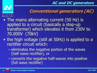
Advantages of AC Power • Motors: • AC is ‘natural’ for rotary motors. • Voltage Transformation: • AC transformers allow efficient changing of voltage to enable better power transmission. • Power Transmission: • AC power can be transmitted hundreds of miles. • DC transmission limited to ~1 mile.
Motor to Generator: Rotating DC • Armature current (Ia) produces force (Fd) in the armature causing rotation. • What if we remove the voltage source (VT) and we provided the torque? Equivalent circuit representation
Motor to Generator: Rotating DC • What if we remove the voltage source (VT) and the torque was provided?
Basic Single-Phase AC Generator • Turning the armature results in induced emf (eAA) across the load (Faraday’s Law). • The voltage eAAwill be single phase AC given as: eAA= Vmsin t[V, volts] • What determines ? Rotor
Three-Phase AC Generator • What if we added two additional armature coils? Single Phase Three Phase
Three-Phase AC Generator • The three-phase generator has voltages as a function of time:
Three-Phase AC Generator • Phasor representation of the three-phase generator:
The phase sequence is the time order in which the voltages pass through their respective maximum values. Phase sequence is important because it determines the direction of rotation of a connected motor. Phase Sequence
The ABC sequence or positive sequence, is produced when the generator rotates counter-clockwise. Positive Phase Sequence (ABC)
The ACB or negative sequence, is produced when the generator rotates clockwise. Negative Phase Sequence (ACB)
Large AC Generator • Unlike the generator model with a fixed magnetic field and rotating armature, it is more practical to fix the armature windings and rotate the magnetic field on large generators. • Rotating armatures require brushes and slip rings to conduct current from the armature to the load. • The fixed armature advantage is that the generated voltage can be connected directly to the load with no slip rings or brushes. • The voltage applied to generate the rotating field is a small DC voltage called the field excitation voltage.
Generator Stator The stator is the stationary part of induction motor. A stator winding is placed in the stator of induction motor and the three phase supply is given to it. Stator is slotted with integer multiple of 6 slots. Three pairs of slots contain identical coils of wire, each with NS turns. These windings are called the armature.
Generator Rotor Rotor contains rotating electromagnet called the field winding and is connected to the mechanical load through a shaft. The electromagnet is powered by a DC current via slip rings and brushes. Unlike in the DC motor application, brushes are not commutating and are not as subject to wear (less friction).
Slip Rings Allow DC current to flow to the field windings on the rotor to produce the magnetic field.
Generator Output The amplitude of voltage output is a function of the current supplied to the field windings. The stronger the current, the larger the magnetic field, the larger the output voltage. http://people.ece.umn.edu/users/riaz/animations/alternator.html
Generator Frequency The frequency f (in Hz) of the AC voltage is a function of speed of the rotor N (in RPM): N = 60 f [RPM] If the rotor contains multiple number of even poles (2, 4, 6, etc.) then:
Synchronous Speed Synchronous Speed (speed of rotation of B) versus Poles for a 60Hz Machine:
Example Problem 1 a) For a 4 pole, 60 HZ generator, what is the speed in rpm of the rotor? b) What would be the frequency of a 6 pole machine spinning at the same rpm? 90 Hz