Download
1 / 35
350 likes | 467 Vues
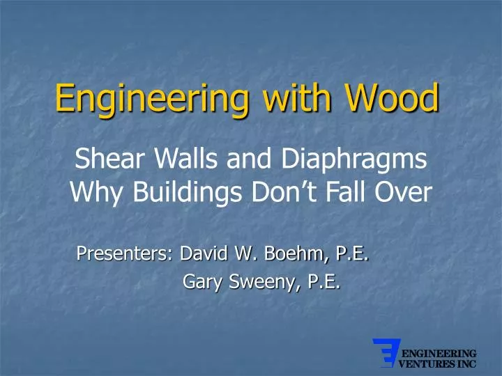
Engineering with Wood. Shear Walls and Diaphragms Why Buildings Don’t Fall Over. Presenters: David W. Boehm, P.E. Gary Sweeny, P.E. Plan View. Assume seismic load is also 200 plf. l = 120’. 200 x 40 2 x 120. v ew = w ew x b. =. =. 33 #/FT. 2 x l. 200 x 120 2 x 40.

E N D
Engineering with Wood Shear Walls and Diaphragms Why Buildings Don’t Fall Over Presenters: David W. Boehm, P.E. Gary Sweeny, P.E.
l = 120’ 200 x 402 x 120 vew = wew x b = = 33 #/FT 2 x l 200 x 120 2 x 40 vns = wns x l = = 300 #/FT veu wew= 200#/FT b=40’ vns wns = 200#/FT DIAPHRAGM UNIT SHEARS 2 x b
PANEL LAYOUT AND FASTENER SCHEDULE North-South Loading Case 1 v = 300 #/FT Assume 8 d nails 15/32 plywood 2” nominal framing Choose: Blocked Diaphragm 8 d nails @ 4” panel edges 8 d nails @ 6” interior East-West Loading Case 3 v = 33 #/FT Unblocked 6” max spacing at panel edges
DIAPHRAGM CHORD SIZE Moment due to N-S wind m = wl 2 = 200 1202= 360,000 FT-LBS 8 8 Axial load in chords = C = T = M = 360,000 ft-lbs = 9,000 LBS b 40 ft Assume allowable ft = 1150 psi Area required = 9,000# = 7.8 in2 1150 psi Assume 2 x 8 wall plate, bolted Area of 2 x 8 with bolt hole A = 1.5 x (7.25 - .875) = 9.56 in2 Use double 2 x 8 top plate / chord to allow for splice
A 40’ T C Shear Walls • North wall v=33 #/ft • Nominal nailing required • East and west walls v=300 #/ft Vns = 300#/ft(40’) = 12000# 20’ Nailing pattern 7/16 sheathing2 x studs8d nails @ 4” required Shear wall elevation
Tiedown Force ΣMA = 0 0 = (12000 x 20) – (T x 40) T = 6,000#