Download
1 / 50
590 likes | 1.46k Vues
J1000: 1 kW AM Digital Transmitter NAB2005 April 18 - 21, 2005 Outline Feature Overview Technical Theory HD Radio with Case Study Jazz™ 1000 Feature Summary Intuitive Control and Monitoring

E N D
J1000:1 kW AM Digital Transmitter NAB2005 April 18 - 21, 2005
Outline • Feature Overview • Technical Theory • HD Radio with Case Study
Jazz™ 1000 Feature Summary Intuitive Control and Monitoring Provided through 240 x 64 graphic user interface, diagnostic flow diagram and a comprehensive 128 event log for simplified troubleshooting and maintenance Built-in Power Preset Scheduler Automatically preset and schedule your FCC power allocations Simple frequency change Ideal for multi-station backup Redundant Architecture Two complete and independent wideband 500 W power modules Compact and Light Weight 19” rack mountable forquick, cost effective delivery andminimal space requirements Plug-and-play HD Radio and DRM compatibility
Intuitive Control and Monitoring Exciter/Control Panel System Diagram An LED diagnostic status flow diagram continuously monitors the system Diagnostic Display Menu-driven graphic user interface screen allows control and monitoring of J1000 critical parameters and modes of operation Controls Push-button switches allow convenient access to the transmitter’s RF status and operator control source
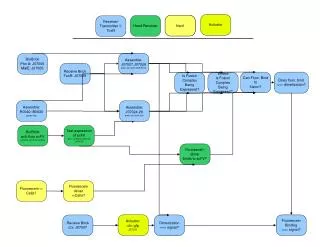
Diagnostic Flow Diagram Simplified troubleshooting and maintenance Diagnostic Flow Diagram • Front Panel Alarms • Exciter • Low voltage power supply • AC mains • Power supply • External alarm • Changeover • Mod/PA • Output network
Diagnostic Display Interphase PDM Drive PWB Main Screen 14:55:27 Excit A Man Forward Power: 1003 W 0 500 1200 Refld Power: 25.0W 0 100 200 VSWR: 1.05:1 1 1.50 2.00 Power:1003W Man 3 Menu Power • Top Level Screen indicates: • Transmitter status bar • Three meter selections • Meter selections scroll with Up/Down buttons
Status Bar The Status Bar is present on all screens Displays: Status Bar • Current time • Output power setting • Manual or auto preset power Selection • Active exciter • Exciter changeover option Forward Power: 34.0W 0 600 1200 B+ Voltage : 18.6V 0 25 50 Total Current: 2.88A 0 50 100 14:55:27 Excit A Man Forward Power: 1003 W 0 500 1200 Refld Power: 25.0W 0 100 200 VSWR: 1.05:1 1 1.50 2.00 Power:1003W Man 3 14:55:15 Power: 34.0W Man 1 Excit B Aut Power Menu Fault Menu Status Power Status box will only appear when fault has been recognized
128 Event Log 14:55:15 Power: 1000W Man 1 Excit B Aut Menu Exciter control Events Log Settings Change meter Module status Events Log Back Select • Main Menu Selection • Press Select to enter Events Log
128 Event Log Events Log 17Dec03 90:40:05 01Jan04 80:00:02 Modulator Fail A 01Jan04 80:00:02 Ext. PDM Inhibit 14:55:15 Power: 34.0W Man 1 Excit B Aut 17Dec03 91:00:42 Over Voltage P/S A Back Alarms Only • Events listed chronologically • 128 events are stored in memory • The newest event is always event 001 • Pressing Alarms Only will display only alarm events
Power Preset Scheduler Power Preset Scheduler 14:55:15 Power: 1000W Man 1 Excit B Aut Power January 1: 0:00 Preset February 2: --:-- Scheduler: March 3: --:-- April 4: --:-- May 5: --:-- June 6: --:-- 1: 05:30 Back All Months Select 6 preset RF power levels from 0 W to 1,100 W can be programmed to automatically meet FCC power allocations throughout the day, 12 months of the year. • When a time has been entered for the first month, all months can be selected to copy this time setting for all months • Using Up/Down buttons will move selection through the six power levels • Press Select to enter time selection
Control Section • Local: • Sets and restricts control of J1000 functions that can be controlled remotely, to switches on exciter front panel • Remote: • When selected, all pushbuttons on exciter front panel, except the RF Off switch, are disabled and have no influence • RF On: • Turns on the J1000’s RF power stage and cooling fans • RF Off: • Turns off J1000 RF power stage
Redundant Architecture • A dual exciter system with automatic switchover is available to suit the highest redundancy requirements. Exciters feed two completely independent and redundant signal chains from AC to RF. • Redundant modular design has two complete and independent 500 watt broadband power modules, each with its own high efficiency RF amplifier, modulator, switch mode power supply and integral ventilation fan.
Excellent Sound Quality • Universal switch mode power supplies automatically adjust operating voltage to optimize performance at any power level • A synthesized exciter, using advanced DDS technology produces RF drive at the desired operating frequency ensuring the best possible signal reproduction • Feed an external GPS reference clock signal to the J1000 controller for synchronous operation • Plug-and-play HD Radio and DRM compatibility
J1000 – Operational Features • Switch mode power supply operates from 170 V ac to 270 V ac • Low voltage power supply operates from 83 V ac to 270 V ac (auto-switching) • Low voltage power supply continues providing logic circuits during brownout • RF amplifier is wideband with digital RF drive - never needs tuning
Compact and Light Weight • Compact design allows for quick, cost effective delivery (next business day shipment from factory) andminimal space requirements • The control/exciter section is 19 inches wide and 7 inches high (4U) and is side mounted for convenient access to low level circuitry • The J1000’s power selection mounts in a standard 19” rack and is only 15 ¾ inches high (9U)
Quick Frequency Tuning • Simple change to any frequency between 531 kHz and 1,610 kHz • Requires field upgrade kit, frequency generator and counter, qualified technician and 1 hour • Easy-to-use digital controller. exciter, synthesized with dial up carrier frequency selection • RF filter only needs minimum component changes to tune to new frequency band
J1000 Options J1000 Standby DDS Exciter Section: • Built-in with automatic changeover • Includes DDS synthesizer, interphase PDM driver and low voltage power supplies J1000 Interface Protection Unit: • Includes RF isolation, AC surge protection and wall mount enclosure (including interconnecting RF cable)
J1000 Options J1000 Deluxe Cabinet: • Aluminum rack assembly includes dress panels, rear door and blank front filter panels • Color coordinated to Jazz theme Rack Mounting Kit: • Includes mounting angle support for RF assembly and slides for exciter/control section
Nautel Deluxe Rack Kit Dimensions: H = 72.5” W= 23.5” D= 28” Nautel aluminum deluxe rack kits are available to hold the control/exciter section and the power section, with plenty of extra room for your auxiliary equipment. Footprint = 23.56” wide * 28.8” deep Weight (rack only): 205 lbs (93 kg)
J1000 ‘Extras’ Spares Kit: • Includes lamps, fuses, semiconductor, ventilation fan, and miscellaneous hardware J1000 500 W Power Module: • Comes with high efficiency RF amplifier, modulator, switch mode power supply and integral ventilation fan
J1000 ‘Extras’ Frequency Change Kits: • PACKAGE A: Frequency change kit for low band (540 kHz to1,060 kHz). Includes set of RF power capacitors • PACKAGE B: Built-in frequency change kit with automatic changeover for high band (1,060 kHz to 1,610 kHz). Includes DDS RF driver, PDM modulator driver and low voltage power supplies.
J1000 Technical Manuals Operator’s Manual • Product overview • Site and pre-installation • Operating instructions • Testing and adjustments • System level troubleshooting Repair Manual • Theory of operation • Component level troubleshooting • Parts & wiring information • Electrical & mechanical schematics One printed manual set provided with transmitter purchase
Online Documentation Nautel Users Group: • Online access to technical frequently asked questions (FAQ), information sheets and field upgrade documents Online Documentation: • NUG website provides online access to all technical documentation for the J1000 transmitter
Online Training • Covering: • Product overview • Site and pre-installation • Theory of operation • Testing and adjustments • Operating instructions • System level troubleshooting • Component level troubleshooting • Component part lists and wiring route sheets
Extended Warranty Plans • ADD 12 or 24 months to Nautel’s STANDARD 13-month warranty plan • Includes: • Module exchange program for common modules and PWBs (CAN/US only) • Toll-free hotline (CAN/US only) • Necessary labor conducted at Nautel facilities or by Nautel authorized personnel to repair back to specifications • Necessary components • Modifications to improve performance • Return shipping
Modulation Theory Interphase PDM Drive PWB PDM signals generated for carrier only - no audio applied • PWB produces dual PDM signals phase shifted by 180°: • Half of the modulators in the transmitter work on each PDM signal (1/2). • Reduces the effect of the PDM on the spectrum.
Modulation Theory Interphase PDM Drive PWB PDM signals generated for carrier with audio applied
Switch Mode Power Supply • Power Supply automatically selects modulator operating voltage for specific output power • Output voltages are 150 Vdc, 250 Vdc and 350 Vdc • Designed to switch when duty cycle is nominally 45%
RF Power Assembly Modulator Assembly
Exciter/Control Interphase PDM Drive PWB Dump adjustment used to optimize transmitter operation during high trough modulation. Gain used to ensure output from each exciter is equal.
Exciter/Control Remote Interface PWB • The Audio Chopper is activated to prevent the low frequency audio (with high modulation) from causing undo stress on the RF Amplifiers. • This is done by chopping part of the audio’s positive waveform. TP3 - 20 Hz audio at 95 % modulation depth with 60 kW carrier.
Remote Interface • Audio Chopper Circuit: • Limits the positive amplitude/duration of audio signal • Monitors the RF output signal • FET Q3 turns to clamp offending signal to ground
Digital Performance • Plug-and-Play Digital Compatibility • Fully compatible with HD Radio and DRM • Nautel Interphase Pulse Duration Modulator employs • linear extended band filter • Maintains envelope bandwidth of 40 kHz • Special circuit optimizes IPM and ensures minimal phase error to provide superior signal-to-noise ratio
Nautel AM HD Radio Overview GPS Antenna Carrier Frequency and Phase Information NE IBOC AUX Support Unit NE IBOC HD Radio AM Signal Generator Nautel AM Xmit STL AES Source Magnitude Antenna Side Sync'd AES Studio Side AES HD Radio Audio Processor AES (ANALOG) Exciter “B” Mono Program Transmission Side
AES Source • NO AES = NO HD Radio! • Must be between 32 kbps and 96 kbps
PAD Options • Audio Program: • Station call sign • Scrolled message 12:24 KNMI Easy listening Top 40 Easy listening Top 40
PAD Options • Audio Program PLUS Program Associated Data: • Requires content server at station • NE IBOC HD Radio signal generator polls Ethernet or serial port for data KNMI 12:24 Hoobastank The Reason Hoobastank The Reason
Antenna Issues • Bandwidth • Occupied bandwidth for HD Radio signal is 15 kHz • VSWR reflection • Should be no greater than 1.4:1 at 15 kHz • Hermetian Symmetry • Poor symmetry will result in error rates
Nautel AM HD Radio NE IBOC HD Radio Signal Generator NE IBOC Auxiliary Support Network Nautel AM HD Radio Signal Generator
NE IBOC Signal Generator • Features: • All user adjustments available from 640 + 480 touch screen interface: • Home page display of exciter configuration • Convenient sub menus for all set up adjustments • Alarm display for fault conditions with sub menu for detailed diagnostic information • System status log provides 3-second updates
NE IBOC Signal Generator • Features: • All user adjustments available from 640 + 480 touch screen interface (CONT): • XLR connectors on rear panel for convenient interface to station • Industry standard PS/2 connectors for external • Standard 5U 19” EIA rack mountable for easy installation in existing racks
NE IBOC Signal Generator • Features: • Digital auxiliary unit including: • GPS antenna • GPS synchronization • Built-in AES/EBU relay switching • Valid AES data indicator • 44.1 kHz clock with indicators • Rate converter
NE IBOC Signal Generator • Dimensions: • NE IBOC Signal Generator: • 19” W x 7” H x 22” D • (48 cm W x 17.78 cm H x 56 cm D) • NE IBOC Auxiliary Unit: • 19” W x 3.5” H x 22” D • (48 cm W x 8.89 cm H x 56 cm D)
Audio Redundancy GPS Antenna Carrier Frequency and Phase Information NE IBOC AUX Support Unit NE IBOC HD Radio AM Signal Generator Nautel XR12 STL Xmit STL Rcv Magnitude Switch HD Radio Audio Processor Host Audio Processor Option 1 Use the NE IBOC Aux Unit to switch to conventional program if digital fails
Audio Redundancy GPS Antenna Carrier Frequency and Phase Information NE IBOC AUX Support Unit NE IBOC HD Radio AM Signal Generator Nautel XR12 STL Xmit STL Rcv Magnitude HD Radio Audio Processor Host Audio Processor Exciter “B” Option 2 Use Exciter “B” as a fully redundant feed for conventional AM on Nautel XR Series transmitters
Audio Processor Options Digital Channel ORBAN 9200D GPS Antenna Carrier Frequency and Phase Information NE IBOC AUX Support Unit NE IBOC HD Radio AM Signal Generator Nautel AM Xmit STL Rcv STL Xmit Magnitude Analog Channel Exciter “B” ORBAN 6200
Audio Processor Options GPS Antenna Carrier Frequency and Phase Information NE IBOC AUX Support Unit NE IBOC HD Radio AM Signal Generator Nautel AM Xmit STL AES Source Magnitude Sync'd AES AES AES (ANALOG) Summer Exciter B OMNIA 5EX+HD L & R
Nautel AM HD Radio Conversion Denver’s Local Christian Radio KPOF Westminster, Colorado Jack Pelon Station Manager Ray Rogers Station Engineer
KPOF HD Radio Conversion • Day 1: February 1, 2004 • Install NE IBOC HD Radio Signal Generator, UPS and audio processors (Orban 6200 and 9200) in cabinet • Problem # 1 - Station feed was analog only – Solution get ADC next day • Problem # 2 – Processor 9200 needs to have digital option (9200D) - Solution getdigital I/O option from Orban • Closed loop test using 6200 as ADC ♫ • Interface transmitter tointerface NE IBOC • Install conventional AM on transmitter Exciter “B”
KPOF HD Radio Conversion • Day 2: February 2, 2004 • Complete set up of NE IBOC to transmitter adjustments • Pick up and install ADC • Perform magnitude amplitude adjustment • Problem #3 – transmitter “chopper circuit” modification – Solution: bias zero crossing detector • Perform magnitude phase delay and analog audio diversity delay adjustments • Have a listen to HD Radio then pack up