Download
1 / 35
390 likes | 776 Vues
Introduction and Building Loads. CE 636 - Design of Multi-Story Structures T. B. Quimby UAA School of Engineering. Course Objective.

E N D
Introductionand Building Loads CE 636 - Design of Multi-Story Structures T. B. Quimby UAA School of Engineering
Course Objective • The objective of the course is to give entry level structural engineers an understanding of the principles associated with the structural design of building systems.
Expected Outcomes At the conclusion of this course, the students will have: • an understanding of the engineering design process as it relates to building structural design, including an appreciation for: • the iterative nature of the design process • the concept that there are more than one way to solve most engineering problems • an understanding of structural loads and their determination. • a basic understanding of the behavior and use of various structural systems • a basic understanding of what is required in a set of construction drawings • a basic understanding of what is required in a set of construction specifications • a recognition of the need for continual learning as a professional • an understanding of the need for professional registration • an understanding of professional and ethical responsibility • the basic ability to: • identify, formulate, and solve building structural design problems • produce a set of construction drawings. • produce a set of construction specifications
Course Content • The emphasis of the course will be slightly different than the text. We will be considering all multi-story structures, not just “Tall” buildings. • Load computations • Preliminary calculation methods • Computer modeling • Different GFRS and LFRS • Calculations and Contract Documents
Tall Buildings • Author: “A tall building .... is one that, because of its height, is affected by lateral forces due to wind or earthquake actions to an extent that they play an important role in the structural design. • History • Defense • Ecclesiastical • Commercial (from 1880 to current) • Residential (from 1880 to current) • Maximize use of high cost land
Factors Affecting Development • Materials • Timber & Masonry limit to ~ 5 stories • Wrought Iron & Steel in mid 1880s • Structural Concrete after 1900 • The Elevator • Made upper stories attractive to rent • Made tall buildings financially viable • Construction Technology • Increase Speed • More efficient equipment • Improved methods
Office vs Residential • Office/Commercial buildings • Large entrances and open lobbies • Reconfigurable space (large column free open areas) • Residential buildings • Partitions are frequent and the same from story to story
The Design Team • Consists of: • Owner • Architect • Structural Engineer • Services Engineer (Mechanical & Electrical) • Team should collaborate EARLY to agree on a form of structure to satisfying the conflicting requirements. • Structural system is subservient to the architectural requirements. • Compromise is inevitable.
The Design Process • Design is an evolutionary (iterative) process. • Do preliminary sizing of members for gravity loads using approximate analysis. • Check lateral strength and deflections, adjust members sizes and configuration as necessary. • Make alterations to original layout as owner and architect refine the design. May require radical rearrangement and complete review of structure. • Make a rigorous final analysis using a refined analytical model and verify deflections and member strengths. • Include the effects of movements due to creep, shrinkage, temperature differentials, and foundation settlement. • Complete Construction Documents
Design Criteria • Architectural • Internal layout to meet functional requirements • Aesthetic qualities • Structural • Strength (Elastic vs. Plastic) • Serviceability (deflections, vibrations, etc....) • Services • Power • Ventilation
Limit State Design • A probabilistic approach • Structural properties • Loading conditions • When a LIMIT STATE is reached, the structures said to have failed. • Strength Limit States • Exceedance of these limit states endanger lives and/or cause serious financial loss. • Probability of material failure and instability must be low. • Serviceability Limit States • Fitness of the building for normal use • Probability of failure may be higher since failure is not catastrophic.
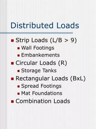
Loading • Buildings are designed to carry all gravity loads and lateral loads to be seen during construction and service. • Must consider sequential loading (particularly during construction) in buildings where the sequence is important. • Types of Loading: • Dead • Occupancy (Live) • Impact • Snow • Wind • Seismic • 1997 UBC Chapter 16
Strength & Stability • “the building structure should have adequate strength to resist, and to remain stable under, the worst probable load actions that may occur during the lifetime of the building, including the period of construction.” • Consider probable load combinations (1997 UBC 1612) • Second order affects • Progressive collapse • Differential movement (shrinkage, creep, settlement, temperature) • Overturning
Stiffness and Drift Limitations • Deflections under gravity loads must be with in tolerable limits for the occupancy. • Deflections under lateral load must be small enough to satisfy • Second order effects (P-delta) • Avoid distress to the structure (cracking, redistribution of loads to partitions, etc....) • Human comfort (acceleration, period, amplitude, visual and acoustical cues, past experience) • Serviceability • Lateral drift requirements (1997 UBC 1630.10)
Tributary Areas • Useful for determining member forces due to UNIFORMLY APPLIED loads (dead, live, pressure, etc....) on SIMPLY SUPPORTED members. • Use structural analysis theory to find the “path” that loads take as they “find their way” down to the foundation through the structural members.
Example #1 • Applied load is uniformly distributed.
Tributary widths of beams supporting joists coming in at odd angles
Column Tributary Area • For a triangular load, the reaction at B is 1/3 of the total load on the beam. This means that the column supports 1/3 of the area. • For a triangular load, this means that the column at B support L/sqrt(3) of the length of the beam.
Example #2 • Identify the Tributary Areas for: • For each beam • For each column
Areas Trib. to column at C2 • These columns probably support exterior wall sections as well. Depends on details. • Gravity loads tend to accumulate linearly as you go down the building. • Live loads may be reduced.
Example #4 • Have fun with this one! • Find area supported by beams on radial grids.
Dead Load Calculations • Dead loads are the weights of all items permanently attached to the structure. • Roof, Floor, and Wall dead loads are typically expressed in terms of “unit” loads (the weight per unit of surface area). • Permanently attached equipment and machinery are generally treated as point loads or uniform loads over a limited area.
Unit Load Calculations • All unit load calculations should be accompanied by a sketch or reference a drawing showing a typical calculation. • Each item is expressed in terms of its weight per unit surface area. • Must compensate for slopes over 4:12. • Final result should be not include decimals! (your overall estimate is not any more accurate than three significant figures (if that!) • Should add an appropriate “Misc..” amount for minor items not specifically accounted for in itemized calculation.
Live Loads • Live loads are any loads that are not permanently attached to the structure. • Live loads may be expressed in term of area loads or point loads. • Live loads are placed for maximum effect. • Tabulated code values result from experience and typical field surveys. • See 1997 UBC 1606 & 1607 • Live loads may be reduce for design of members that have large tributary areas. 1994 UBC 1607.5
UBC Floor Live Load Reduction • Use when: • Member supports more than 150 ft2 • Live load not greater than 100 psf • Member does not support a place of public assembly • Use the lessor of: • R = 0.08(A-150) • R = 23.1(1+DL/FLL) • R = 40% for members receiving load from one level only, or 60% for members receiving load from more than one level.
Alternate Floor Live Load Reduction • As an alternative, the following equation may be used for member with an “influence area” greater than 400 ft2. (New with the 1994 UBC) • L = L0(.25+15/sqrt(AI)) • Maximum reduction is 50% for members supporting one level and 60% for members supporting multiple levels. • AI is the influence area. For a column AI is four times the trib. area. For a beam, AI is two times the trib. area. For a 2-way slab, AI equals the panel area. For a precast T-beam, AI is the span times the full flange width.
UBC Roof Live Loads • 1997 UBC 1607.4 & Table 16-C • If unbalanced loading causes maximum effects, it must be considered. • Snow loads must be considered where they exceed the values for the roof live loads. (See 1997 UBC Appendix to chapter 16, Div. I - Snow Load Design) • When analyzing for snow loads, must consider unbalanced loading and drifting. • Snow Loads may be reduced with increasing roof slope. • RS = S/40 - .5 • RS = snow load reduction (psf) per degree slope over 20 • S = total snow load (psf)