Download
1 / 54
880 likes | 1.96k Vues
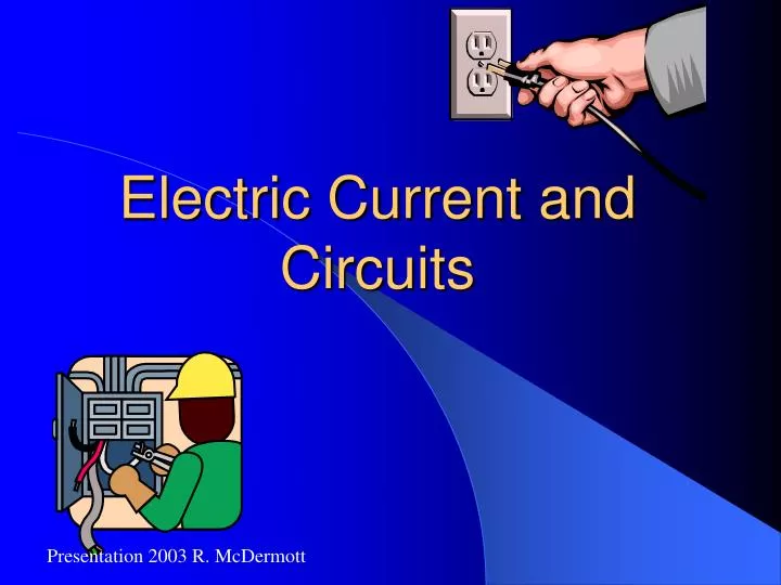
Electric Current and Circuits. Presentation 2003 R. McDermott. What is Current?. Electric current is a flow of electric charge By convention from + to – Actually electrons flow away from – and toward + Current doesn’t slow down, nor does it get “used up” Symbol of current is I

E N D
Electric Current and Circuits Presentation 2003 R. McDermott
What is Current? • Electric current is a flow of electric charge • By convention from + to – • Actually electrons flow away from – and toward + • Current doesn’t slow down, nor does it get “used up” • Symbol of current is I • Unit is the ampere (A)
Current is Flow of Charge in a Conductor • I = DQ/Dt • Example: A steady current of 4.0 amperes flows in a wire for 3 minutes. How much charge passes through the wire? Answer: 720 C
Current Flows in an Electric Circuit • A continuous conducting path is called a circuit • Current flows through the wires from one terminal of the battery to the other
Current Doesn’t Flow in an Open Circuit • A wire with a break in the conducting path is called an open circuit • Since no current can exit the wire, none can enter the wire either – no current flow • Unscrewing a bulb creates an open circuit
What Really Happens • Potential difference of the battery sets up a non-uniform charge distribution on the surface of the wire • That produces an electric field in the wire • Free electrons leave negative terminal of battery, pass through circuit and re-enter battery at positive terminal
Batteries • Batteries produce charge continuously from chemical reactions • Consist of two dissimilar metals in an electrolyte (liquid, paste, or gel)
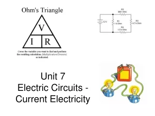
V I R Ohm’s Law • Current flow is proportional to voltage • Inversely proportional to resistance • Resistance is constant of proportionality • V = I R • I = V/R • R=V/I
Ohm’s Law V = IR • What happens to current if you increase V? • What happens if you increase R? I Graph? V
UNITS • Voltage Volt (V) • Current Amperes (A) • Resistance Ohm()
Resistance • Since wires are filled with atoms, there will be collisions and therefore resistance to the flow of current • The resistance increases with wire length and temperature, but decreases as the wire gets “fatter” (increased cross-sectional area) • As current flows through resistance, energy is removed (just like friction)
Resistance • You can think about current as being like students moving through a filled hallway: • No one enters until someone leaves at the other end • The length and width of the hallway affect the resistance to student walking
Resistance • Resistance of a metal wire: R = rL/Ar is resistivity L is length of wire A is cross-sectional area Silver has lowest resistivity Copper is almost as low Gold and Aluminum low too
Superconductivity • Resistance of certain materials becomes zero at low temperatures • Niobium-titanium wire at 23K • Yttrium-Barium-Copper-Oxygen at 90K • Bismuth-strontium-calcium copper oxide • Can make strong electromagnets that do not require power • Japanese Maglev Train goes 329 mph
AC - DC • DC is direct current. • Steady, one direction • Comes from battery or power supply • AC is alternating current • Back and forth • Sine wave with frequency of 60 Hz • House current
Electric Power • Power = energy transformed/time = QV/t P = IV unit: watt Since V = IR P = IV = I2R = V2/R • Which is more important, current or voltage? • In power transmission, why is high voltage advantageous?
Batteries in Series • When batteries or other sources of potential are connected in series, the total potential difference is the algebraic sum of the separate potentials. • 6V + 6V = 12V • Another example: a 9 volt radio battery consists of 6 1.5 volt cells in series.
Batteries in Parallel • The voltages do not add, but current can be drawn for a longer time (more chemicals)
Circuit Potential • The battery produces a difference in “electrical height” from one end of the circuit to the other • Current (conventional) then flows “downhill” from the positive terminal to the negative • In a circuit, the potential difference is often referred to as the Electromotive Force, or EMF.
Circuit Potential • The diagram to the right illustrates the point: • The + terminal is the top of the electrical hill • The - terminal is the bottom of the electrical “hill”
Series Resistive Circuit Full current goes through all circuit components
Series Theory: • The current must travel at the same speed throughout the circuit ( I1 = I2 etc) • Normally, a “drop” would produce an increase in speed, but the energy of the “drops” is removed by the resistors
Theory: • Note that the drop heights (voltage drops) do not have to be equal • But they do have to add up to the total drop, so that Vt = V1 + V2
Theory: • In this diagram, resistor two has greater resistance, removes greater energy, and causes a greater potential drop than does resistor one • A resistor’s effects are proportional to its resistance
Theory: • Adding a 3rd resistor: • The total potential drop is a fixed value • Resistor three has to take some of the total drop • Resistors one and two now have smaller potential drops
Theory: • Another point of view: • Adding resistor three increases circuit resistance since current must now pass through three resistors • Increased resistance decreases circuit current • Less current means less potential drop for resistors one and two (and less energy)
Circuit Diagrams • A circuit diagram consists of symbols that represent circuit elements: • Battery: • Resistor: • Rheostat: • Capacitor: • Switch:
Series Diagram This is the circuit diagram for our two- resistor series circuit
Series Diagram And this one is our three-resistor series circuit
Series Sample #1 • Which direction does current flow? • Find total resistance • Find circuit current • Find V1 and V2 • Find circuit power • Find P1 and P2
Circuit resistance in a series circuit is: Rc = R1 + R2 Rc = 2 + 4 Rc = 6 Circuit current in a series circuit is: Ic = Vc/Rc Ic = 12v/6 Ic = 2a Series Sample #1:
The voltage drop in resistor one obeys Ohm’s Law: V1 = I1R1 V1 = (2a)(2) V1 = 4v As does the voltage drop in resistor two: V2 = I2R2 V2 = (2a)(4) V2 = 8v Sample #1:
Since we know the circuit current and the circuit voltage, power is best found by: Pc = IcVc Pc = (2a)(12v) Pc = 24w For the resistors, however, it might be a bit safer to choose the equation: P = I2R P1 = I12R1 and P2 = I22R2 P1 = (2a)2 2 P2 = (2a)24 P1 = 8w P2 = 16w Sample #1:
Ratios? • In a series circuit, ratios can be used if you’re very careful • The resistances, voltage drops, and power are directly proportional: R1 = 2 R2 = 4 Rc = 8 V1 = 4v V2 = 8v Vc = 12v P1 = 8w P2 = 16w Pc = 24w
Series Sample #2 • Which direction does current flow? • Find total resistance • Find circuit current • Find V1 ,V2 and V3 • Find circuit power • Find P1 ,P2 and P3
Parallel Resistive Circuit • Same voltage across all circuit elements IT = I1 + I2 + I3 + V/RT = V/R1 + V/R2 + V/R3 1/RT = 1/R1 + 1/R2 + 1/R3 +
Parallel Theory: • In a circuit, the total potential difference supplied by the battery is fixed • To the right, each branch goes from the top of the battery to the bottom • Therefore each potential drop is equal: Vt = V1 = V2
Theory: • To the right, the current splits at the first junction, and then recombines at the second • The total current can’t change: It = I1 + I2 • The current dos not have to divide equally; the branch with less resistance gets more of the current
Theory: • Follow-up explanation: • Each branch has the same voltage • I = V/R • So the branch with less resistance gets more of the current
Theory: • Two or more paths to follow • Effectively makes the wire thicker (cross-sectional area) • More total current can flow • So the more parallel paths (resistors), the less the total resistance of the circuit must be! • In fact, the total resistance will always be less than the smallest resistor in the parallel combination.
Theory: • If resistor two has a greater resistance than resistor one: • It will draw less current and power than resistor one • But they have the same voltage • In a parallel circuit, a resistor’s effects are inverse to the size of the resistor
Theory: • Adding a 3rd resistor: • Resistors one and two get same voltage as before, therefore the same current and power • Resistor three has full battery voltage, so draws additional current from battery • Total circuit current and power rises • Adding (or removing) a resistor has no effect on other resistors
Parallel Diagram This is the circuit diagram for our two resistor parallel circuit
Parallel Diagram And this one is our three resistor parallel circuit
Parallel Sample #1 • Find the total resistance and total circuit current • Find I1 and I2 • Find V1 and V2 • Find circuit power • Find P1 and P2
The total circuit resistance can found by using: the equation: 1/Rc = 1/R1 + 1/R2 + … 1/Rc = ½ + ¼ = ¾ Rc = 4/3 = 1.33 The circuit current by: Ic = Vc/Rc Ic = (12V)/(1.33 ) Ic = 9a Parallel Sample #1:
I = V/R I1= 12V/2 I1= 6a I2= 12V/4 I2= 3a P = V2/R Pc = (12v)2/(1.33) Pc = 108w P1 = (12v)2/(2) P1 = 72w P2 = (12v)2/(4) P2 = 36w Parallel #1:
Ratios? • In a parallel circuit, ratios can be used if you’re very careful • The current and power are inversely proportional to the resistance: R1 = 2 R2 = 4 Rc = 1.33 I1 = 6a I2 = 3a Ic = 9a P1 = 72w P2 = 36w Pc = 108w
Parallel Sample #2 • Find the total resistance and total circuit current • Find I1 , I2 and I3 • Find V1 ,V2 and V3 • Find circuit power • Find P1 , P2 and P3
Capacitors in Series • Charge same on each capacitor • Q = CTV • V = V1 + V2 + V3 • Q/CT =Q/C1 +Q/C2 + Q/C3 • 1/CT = 1/C1 + 1/C2 +1/C3