Download
1 / 20
200 likes | 408 Vues
C3: CLASTIC SEDIMENTS. 1 Fluid flow Sediment transport & bedforms Coastal sedimentation esp w.r.t. N Norfolk 4 Muds and mass movement – debris flows and turbidites Reading: P.A. Allen: Earth Surface Processes. Blackwell Science, 1998.

E N D
C3: CLASTIC SEDIMENTS • 1 Fluid flow • Sediment transport & bedforms • Coastal sedimentation esp w.r.t. N Norfolk • 4 Muds and mass movement – debris flows and turbidites • Reading: • P.A. Allen: Earth Surface Processes. Blackwell Science, 1998. • J.R.L. Allen: Principles of Physical Sedimentology. Allen & Unwin, 1985. • M. Leeder: Sedimentology and Sedimentary Systems. Blackwell Science, 1999. • G.V. Middleton and J.B Southard: Mechanics of Sediment Movement. • SEPM Short Course 3, 1984. • Contact: • mccave@esc.cam.ac.uk
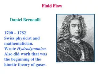
C3 Clastic Sediments Lecture 1 FLUID FLOW and the BOUNDARY LAYER
CLEAR FLUID UNDERGOING SHEAR Linear velocity gradient U/L ~ F force applied to move upper plate At any point in the viscous fluid: t = m du/dy shear stress velocity gradient viscosity of the fluid Laminar flow is dominated by molecular viscosity.
Flow Downslope Suppose we have fluid running down an inclined plane: The flow is steady, uniform in x-direction, but not in the z-direction as fluid sticks to the bed (no-slip condition). frictional force exerted on bed: τo (subscript “o” means at the bed) Downslope component of fluid weight: gD sin θ Since steady, forces balance: τo = γD sin θ = γDS (Duboys Eq.) (because for small angles sin θ = S, the slope; γ = g)
STREAM POWER Stream Power is the rate at which a flow does work on its bed. Work: rate of conversion of potential energy into kinetic energy. Principal control on sediment transport and formation of bedforms. Rate of loss of gravitational potential energy per unit area of stream bed: rgSdu S is channel bed slope, d is flow depth. rgSd is downslope component of gravity force acting on unit water column. Opposed by an equal shear stress t0 exerted by unit bed area. Stream Power w = t0u Need to know velocity profile in stream
SETTLING GRAIN Settling velocity of grain with diameter D and density rs through a still fluid with density rf: FD = pD3g ' /6 Drag force submersed weight of grain g ' = (rs – rf)g submerged specific weight Fluid is static: ignore rf Remaining variables: FD, u, m, and D Dimensionless product: FD/muD = 3p Stoke’s Law: u = D2g '/18m Only when flow is laminar: small Reynolds number. Beware: sometimes D is grainsize, sometimes depth, and vice versa for d.
DIMENSIONS OF VARIABLES IN SETTLING ANALYSIS For laminar flow to occur around a particle the “particle Reynolds Number” Rep < 0.5 Rep = wsd (here ν = μ/ρ, the kinematic viscosity): Re is ratio of (inertial/viscous) forces ν Consider the dimensions involved, you will see Reynolds Number is dimensionless, LT-1 x L/L2T-1. Denoting the group (ρs- ρ)g as γs‘ (the submerged specific weight), the pertinent variables in Stokes Law are ws = f (γs', μ, ρ, d) Some of these go to make a Reynolds Number, the others can, by inspection, be assembled into another dimensionless group around the outstanding variable γs'. Ξ = γs'd3ρ ; using ν = μ/ρ (kinematic viscosity), Ξ = γs'd3 μ2 ρν2 Plotting data from many experiments using different combinations of particle and fluid density and viscosity gives a “universal” settling velocity curve plotted on Rep and Ξ.
Dimensional plot: ws vs d. Curves for different grain shapes For gravel (d > 2 mm) in water ws d½ , for silt and clay (d < 63 μm) ws d2, and for the material in between (i.e. sand, roughly ws d).
THE BOUNDARY LAYER The no-slip boundary condition: fluid at a boundary takes on the speed of the boundary. Thus, when fluid slows over a stationary bottom, such as sediment, it sticks to the bed, and velocity is zero there. U Thus, we have a region of the flow where velocity decreases from the free-stream value U to 0 at the bed: this is the boundary layer Layers are successively dragged along linked via molecular or eddy viscosity and when dragged in parallel by molecular viscosity this is laminar flow.
BOUNDARY LAYER • In boundary layer: • Total stress = • Viscous stress m(du/dz) + • Turbulent stress -r(u'v'). • Turbulent stress: • = (m+ h)du/dz • is ‘eddy viscosity’, • >>m hdu/dz = -r(u'v') The origin of turbulence is linked with presence of a boundary. The effects of the boundary are felt in motion of fluid over certain distance away from boundary i.e. in the boundary layer. Hydraulically smooth boundary: roughness elements contained within viscous sublayer Hydraulically rough boundary: roughness much greater than nominal VSL thickness
VELOCITY PROFILE IN LAMINAR FLOW At channel bed: t0 = rgSd At height y: ty = rgS(d-y) ty = t0(1-y/d) Shear stress varies linearly from maximum at bed to zero at surface. Using t = m(du/dy), du/dy = rgS(d-y)/m Integrate to obtain velocity at any point above bed, assuming that fluid density and viscosity are constant: u = (rgS)/m (yd – y2) + C If C = 0, then velocity profile is parabolic.
TURBULENT FLOW In turbulent flow, fluid particles take part in rapidly varying 3-D motion in turbulent eddies. In these eddies, local accelerations are very important; viscosity plays a minor role. Re = ruD/m > 500 for pipe flow; > 2000 for open channel flow Turbulent flows are well mixed.
VELOCITY PROFILE IN TURBULENT FLOWS In the boundary layer, the velocity gradient depends on the shear stress at the boundary There are three parameters: velocity gradient (du/dz), shear velocity (u*), and height above the boundary (z). One dimensionless product: u*/(z du/dz) = k≈ 0.4 (du/dz = k z/ u*) k is von Karman’s constant. It can be shown that (see derivations at back of lecture notes) uz/u* = 1/kln(z/z0), the law of the wall (ln is loge) where the ‘roughness length’ z0 is the height above the bed at which the extrapolated flow velocity is zero. The velocity profile in a turbulent flow has a logarithmic form.
VELOCITY PROFILE IN TURBULENT FLOWS The flow speed at height z over a rough boundary (roughness elements – e.g. sand or gravel – diameter ks) is linearly distributed as the log of height. It has a slope d(ln z)/dUz and an intercept zo. (Actually you would get this even if the boundary were flat and smooth) Note I’ve used dz/du not du/dz, this is because we often plot with height z upwards. This introduces the very useful parameter U* = (τo/ρ) called the shear or friction velocity. It has the dimensions of a velocity (LT-1), but as you can see is based on the shear stress at the boundary.
VELOCITY PROFILE IN TURBULENT FLOWS Within turbulent boundary layer there is a viscous sublayer (VSL) (close to the bed, slower flow, lower Reynolds Number). In this layer flow is quasi-laminar, with a high velocity gradient. Velocity u in viscous sublayer is f (t0, m, and z) One dimensionless product: mu/t0z, which is constant, roughly unity. Multiplying top and bottom by r gives (νu/ u*2z) ~ 1 because the shear velocity u*, (u*2 = t0/r ), then the velocity u at any height y within the viscous sublayer can be found Thickness of viscous sublayer is ~ 10 (ν/u*), in water generally < 1 mm.
BURSTS AND SWEEPS VSL is not actually laminar. Flow streaks in wall region. Spacing of streaks, l depends on flow properties: Re* = u*l/ = 100 Re* is a ‘spacing Reynolds no.’ Burst-sweep process is main creator of turbulence. Inrush of high-velocity sweeps may locally exceed threshold of sediment motion.
Experimental data for smooth turbulent flow gives a Universal Velocity Profile (note log-linear). Non-dimensional axes, speed normalised by u* and height above bed z normalised as a sort of Reynolds number, u*z/
ROUGHNESS Experiments were run by Nikuradse (1932 and 1933) using pipes roughened by sand grains (thus subscript ‘s’), whose diameter d = ks called the ‘equivalent sand grain roughness.’ But roughness is not always due to grains (e.g. sometimes it is due to ripples), so we use ks in general, not d. This is his data plotted to show changing roughness regimes. Caption explains B. Ordinate is a Roughness Reynolds Number