Download
1 / 118
1.18k likes | 1.54k Vues
Absorption for HAP and VOC Control. 朱信 Hsin Chu Professor Dept. of Environmental Engineering National Cheng Kung University. 1. Introduction .

E N D
Absorption for HAP and VOC Control 朱信 Hsin Chu Professor Dept. of Environmental Engineering National Cheng Kung University
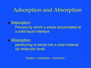
1. Introduction • Absorption is a diffusional mass-transfer operation. Soluble gaseous component is removed from a gas stream by dissolution in a solvent liquid.The driving force for mass transfer: concentration difference • Driving force is positive: absorption Driving force is negative: desorption or stripping • Solvent: water or a low volatility organic liquid • Adequate solubility
2. Aqueous systems • Acidic gases such as HCl, HF, and SiF4 can be absorbed in water efficiently. Alkaline is better. • Less soluble acidic gases such as SO2, Cl2, and H2S can be absorbed more readily in a dilute caustic solution.Na2CO3, NaHCO3, or NaOH < 5~10%CaO, Ca(OH)2, CaCO3: plugging, scalingNH4OH: NH3 slip
CO2: consume more caustic solutionpH < 9: the amount of CO2 absorbed can be kept low • NH3: can be removed with acidic water solutions such as dilute H2SO4, H3PO4, or HNO3Becomes fertilizer ingredients
3. Nonaqueous systems • AminesMonoethanol-, diethanol-, and triethanolamine; methyldiethanolamine; and dimethylanalineFor CO2, SO2 and H2S absorbingHigh absorbent cost: absorbent regeneration is a must • Organic solventHeavy oils, other solvents with low vapor pressure For organic vapors absorbingAbsorber- stripper system
4. Types and Arrangements of Absorption Equipment • Contact between a gas and a liquidBreak the liquid up into small droplets or thin films, which are constantly renewed through turbulence to provide high liquid surface area for mass transfer • Most commonly used devicesPacked and plate columnsOpen spray chambersCyclonic spray chambers
Next slide (Fig. 11.1) Countercurrent packed column: maximizes driving force, because it brings the least concentrated outlet gas into contact with fresh absorbing liquid However, it plugs rapidly when appreciable particulates are present. • Second slide (Fig. 11.2)Spray chamber
Next slide (Fig. 11.3)Cyclonic spray chamber • Second slide (Fig. 11.4)Plate columnBubble cap tower: greater variations in gas flow rateSieve plates: simple, low cost but narrow gas flow operating ranges • Third slide (Fig. 11.5)Baffle tray tower: plug resistant, mass transfer is poor.
5. Design Techniques for Countercurrent Absorption Columns • Co-current towersCross-flow towersCountercurrent towers: the most frequently used • Two main factors:The height: determined by the rate of mass transferThe diameter: determined by the quantity of gas passing up the tower • The upper limit of flow occurs when the tower begins to flood • Higher flow rates result in higher pressure losses • Assume the columns operate isothermally because of the dilute solutions: for the following design equations
5.1 Equilibrium Relationships • Vapor-liquid equilibria for miscible systemsEquality of fugacity in both phases at the same temp. and pressure: i: component i, f: fugacity, v: vapor, L: liquid • Component i in the liquid phase:xi: molar fraction of component i in the liquid, γi: activity coefficient, :standard state fugacity of the pure component only
Component i in the vapor phase:yi: molar fraction of component i in the vapor, : fugacity coefficient, P: pressure of the system • Therefore,
The Gibbs-Duhem equation for n componentsM: solution property, :the corresponding partial molar property, T: temp. • Using excess Gibbs free energy changes, above equation can be written in terms of the enthalpy and volume changes on mixing △H and △V, respectively, and the activity coefficient, γi:
Solutions of nonpolar molecules or solutions at low concentration, △H and △V are smallTherefore, for a binary mixture: • For a solution at low pressure where the vapor is an ideal gas:presuming to be equivalent of the pure component fugacity.At constant temp., above equation can be rewritten:
, the partial pressure of component 1Therefore, Integrate, Therefore, from partial pressure data of one component of a binary solution, the partial pressure of the second component may be calculated.
5.2 Ideal Solutions-Henry’s Law • A general relationship for fugacity of a component in a liquid mixture in terms of the pure component fugacity: (1) • An ideal solution: Therefore, , called the Lewis and Randall Fugacity Rule id: ideal solution
More generally to be consistent with the previous equation • Next slide (Fig. 11.6)Broken lines: ideal solution, : the fugacity of a pure component as it actually exists, : an imaginary state of the real solutionSolid line: a real solution of Eq. (1)
For a pure component • Henry’s LawFor a dilute solutionRewrite:ki: Henry’s Law constant
From previous equation:For solutions at low pressure, and (partial pressure)Therefore, (common form of Henry’s Law)
Rewrite:Define m=ki/P (a common form for Henry’s Law)Therefore, yi = mxi (2) • Henry’s Law is an adequate method of representing vapor-liquid phase equilibria for many dilute solutions encountered in absorption work.However, weak electrolytes: dissociation of the electrolyte may take place upsetting the normal equilibrium relationship.
5.3 Countercurrent Absorption Tower Design Equations • Next slide (Fig. 11.7)A packed tower with countercurrent flow • Mass balance around the cross-section A-A:yAG + xAL = (yA- dyA)G + (xA+ dxA)LTherefore, G dyA = L dxAHowever, the flow rates do not remain constant through the column:d(GyA) = d(LxA)
Integrate from the top of the column down to the cross-section A-A:yAG - yA1G1 = xAL - xA1L1 (3) • Rewrite the flow rates on a solute-free basis (use B):
Rewrite Eq. (3): (4)For dilute solution:Eq. (4) reduces to Eq. (3) which is called the “operating line”.Eq. (4): general equation with a general equilibrium relationship • Eq. (2): Henry’s Law Equation , called the “equilibrium line” (will be shown later)
5.4 Origin of Volume-Based Mass-Transfer Coefficients • Several theories have been devised Whitman “two-film” concept remains an excellent basis 5.4.1 Steady-State Molecular Diffusion • Molecular diffusion serves a basis for mass transfer coefficients Driving force across the interface: concentration gradientComplete thermodynamic equilibrium: no concentration, temperature, or pressure difference in the areas of the diffusion
Assume that only one component is in motion across the interfaceMolecular diffusivity: a relative velocity of the diffusion component with respect to an average velocity of the entire stream is a direction normal to the interface • The molecular motion is accounted for by Fick’s Law.Total flux is the sum of the molecular diffusion and the convective bulk flow.
: the flux of component A in a mixture with component B (unit: moles/time/area)And • Component A with mole fraction, yAMolecular diffusion flux in the Z direction = where, DAB is the molecular diffusivity and is the density of the gas
Absorption of a single component A: it is assumed that A is diffusing through a stagnant layer of B, thus . Previous eq.: can be rearranged and integrated over a distance L with the following boundary conditions, yA = yA0, when z = 0yA = yAL, when z = L • The result is (5)
Because yA0+yB0 = 1 yAL+yBL = 1 A loghrithmic mean concentration can be difined: (6)A mass transfer coefficient can be defined: (7) • Eq. (6) & Eq. (7) can be substituted into Eq. (5):
5.5 The Whitman Two-Film Theory • Next slide (Fig. 11.8)A schematic diagram
The theory summarized:(1) The gas film and the liquid film, on either side of the interface(2) Transfer in the bulk phases by convection currents Concentration differences are negligible except in the vicinity of the interface (3) On each side of the interface, convection currents die out(4) Both films offer resistance to mass transfer Transfer takes place through these films by a mechanism similar to molecular diffusion(5) The interface is at equilibrium and offers no resistance to mass transfer(6) Uniform composition in the main stream(7) At the interface, yAi and xAi are in equilibrium described by Henry’s Law yAi= mxAi
Packed ColumnThe fluid is in turbulent motionMass transfer through the films is defined by ky and kx (turbulent mass transfer coefficient)
5.6 Overall Mass-Transfer Coefficients • Mass-transfer coefficients defined on the basis of interfacial mole fractions have little practical value since these mole fractions cannot be measured. • Two new pseudo-mole fractions are defined as illustrated in the next slide (Fig. 11.9)Overall mass transfer coefficients Ky and Kx are defined based on these new pseudo-mole fractions.yA* = equilibrium mole fraction of the solute in the vapor corresponding to the mole fraction xA in the liquid xA* = equilibrium mole fraction of the solute in the liquid corresponding to the mole fraction yA in the vapor
The mass transfer may now be written: • The construction in Fig. 11.9 (last page) illustrates how to determine xA* for any yA, and yA* for any xA.
The overall coefficients (Ky & Kx) can be related to the individual phase coefficients (ky & kx) making use of Henry’s Law.Therefore: • Also:
Combining: • Rearranging:
5.7 Volume-Based Mass-Transfer Coefficients • Packing has a characteristic area per unit volume of packing: • Flow rate of vapor and liquid phases, viscosity, density, surface tension, and size and shape of the packing determine the value of “a”.These same factors affect the value of the mass transfer coefficients Ky and Kx.
Therefore, two new quantities Ky a and Kx a (volumetric mass transfer coefficients) are common to be used. • If A is the absorption tower cross-sectional area, and Z the packing height, then Az is the tower packing volume.Defining Ai as the total interfacial area: Ai = aAzor in differential form: dAi = aAdz
Rewrite in dNA, with units (moles/unit time) = (moles/unit time‧area) (area):or dNA = Kya(yA-yA*)Adz = Kxa(xA-xA*)Adz
5.8 Determining Height of Packing in the Tower: the HTU Method • For the gas phase, the differential rate of mass transfer of component A is equal to the differential rate of change of the mass of A in the incoming gas stream.dNA = d (GyA) • Rewrite the flow rate on a solute-free basis:GB = (1-yA)G, where GB is a constantthen,
Therefore, (8) • A similar equation based on the liquid phase can be written which would be useful in stripping calculations.
Define a mass transfer coefficient which is independent of concentration:where (1-yA)LM is the log mean concentration defined by:
Define flow rates based on tower cross section: • Rewrite Eq. (8):