Download
1 / 19
190 likes | 593 Vues
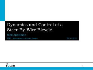
Design and Prototype Build of the Interfaces of a Steer-By-Wire Assembly. Javier Angulo Alan Benedict, Team Leader Amber Russell, Team Manager Kurush Savabi Dr. Sohel Anwar, Faculty Advisor & Sponsor Dr. Hazim El-Mounayri, Course Instructor. Overview. Purpose & Objective

E N D
Design and Prototype Build of the Interfaces of a Steer-By-Wire Assembly Javier Angulo Alan Benedict, Team Leader Amber Russell, Team Manager Kurush Savabi Dr. Sohel Anwar, Faculty Advisor & Sponsor Dr. Hazim El-Mounayri, Course Instructor
Overview • Purpose & Objective • Requirements & Targets • Concept Generation & Evaluation • Product Generation & Evaluation • Conclusions & Recommendations
Introduction Overall Purpose: Create a steer-by-wire system parallel to that of an automobile for use in laboratory
Driver Interface Sub-System Microcontroller Sub-System Rack-and-Pinion Sub-System Introduction(continued) Overall Steer-By-Wire System
Objectives of Design Objectives: • Design of an interface between a standard automotive rack-and-pinion steering assembly and electric motors. • Design of an interface between the same rack-and-pinion steering assembly and angle position sensors • Design of a stand to support the entire system and provide reaction forces to rack
Requirements and Targets • Functionality and safety • Benchmark Visteon-GM Sequel
Concept Development & Evaluation Development Process • Functional Decomposition • Function Concept-Mapping Evaluation Process • Feasibility Testing • Go/No-Go Screening • Decision Matrices • Failure Mode Effects Analysis (FMEA)
Final Concept • Motor to Rack-and-Pinion Interface • Gear Train • Motor to Motor Interface • Gear Train • Sensor to Sensor Interface • Stackable Sensors / Shaft • Sensor to Rack and Pinion Interface • Direct Shaft • Metal Stand Motor Controllers Position Sensors Motor Motor Stacked / Shaft Rack Pinion 1 Pinion 2 Gear Train
Product Generation & Evaluation Motors Requirements • Torque of 52 Nm at 67 rpm • Torque of 20.8 Nm at 133 rpm • Input voltage of <60 VDC Selected Motor Specifications • Torque of 52 Nm at 67 rpm • Torque of 20.8 Nm at 127.4 rpm • Input voltage of 75 VDC
Product Generation & Evaluation Motor Interfaces • Enables redundancy • Allows for maintenance
Product Generation & Evaluation Stand Requirements Max deflection of 12.7mm Max stress of 450MPa Stand Analysis Results Max deflection of 1.83E-4mm Max stress of 89.1MPa (Dynamic) FOS 3 to 5 (267.3MPa to 445.5MPa)
Product Generation & Evaluation Springs • Spring Requirements of 102 kN/m • Selected Spring Specifications of 83 kN/m • Force of 6876 N (to simulate dynamic loading) • Maximum Stress = 104.6 MPa • Yield Strength of Plate = 250 MPa
Product Generation & Evaluation Sensors Hollow-angle sensors • Ease of interface • Zero backlash • Lack of availability • Lower accuracy • Requires less space Conventional Potentiometers • Meet accuracy requirement • Readily available • Cost efficient • Requires gear train interface (backlash)
Questions For further questions, please feel free to ask the design team or refer to the project report. Thank you.
References • Cesiel, Daugherty, Gaunt, “Development of a Steer-by-Wire System for the GM Sequel”, SAE Technical Paper Series, 2006-01-1173. • David G. Ullman, “The mechanical design process”, Third edition, McGrawHill, 2003, USA. • “Delphi Non-Contact Multi-Turn Rotary Position Sensor”, Delphi, www.delphi.com. • “Electric Power Assisted Steering”, Visteon, 2005. • Matweb, www.matweb.com. March 2007. • Miller, Duane K., P.E., Use “Undermatching Weld Metal Where Advantageous: Practical Ideas for the Design Professional”, Welding Innovation, Vol. XIV, No. 1, 1997. • Parker Motion, www.parkermotion.com. April 2007. • Roy Mech, www.roymech.co.uk/useful_tables/form/weld_strength • “Sensors for Position Measurement: Single-turn/Multi-turn Steering-angle Sensor”, Hella International, www.hella.com.