Download
1 / 13
130 likes | 254 Vues
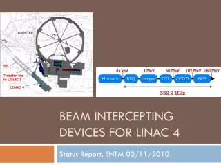
LINAC 4 TL diagnostics. F. Roncarolo, U. Raich L.Soby , J.Tan , C.Zamantzas , F. Lenardon , C.Vuitton , G- J.Focker. L4 BCC – 1 Sep 2011. General Remarks / Overview. DESIGN Completed for almost all instruments ( m ost of TL devices == L4 monitors)

E N D
LINAC 4 TL diagnostics F. Roncarolo, U. Raich L.Soby, J.Tan, C.Zamantzas, F. Lenardon, C.Vuitton, G-J.Focker L4 BCC – 1 Sep 2011
General Remarks / Overview DESIGN • Completed for almost all instruments (most of TL devices == L4 monitors) • Basically all devices will be tested at 3 MeV test stand • Open issues • Number of devices and locations: need frozen layout • Once done: details about interconnections • Profile monitor in dump line (see later slide) • BLM detector type (see later slide) • Equipment of TL with station for laser stripping R&D SCHEDULE / BUDGET • Present advancement/plans/budget for design, fabrication, cabling and installation under control • BI Linac 4 review (with reviewers panel) on October 18th (tbc and announced in the next few days) L4 BCC - 01 Sep 2011
Diagnostics Park • From Layout DB 31-08-11 • 3 BTVs now replaced by 1 WS or SEM GRID (H+V) L4 BCC - 01 Sep 2011
Beam Current Transformers BCT • Copy of LEBT monitors • 100 mm diameter • Up to 200 MHz sampling rate • Acquisition sync. with the distributor, to know how much beam current goes to each PSB ring • Electronics ready for such option • NeedFPGA code update (likely not possible before LS1) • In general • Do we agree on the number of devices? • Foreseen by BI : 6, Layout DB: 7 L4 BCC - 01 Sep 2011
Beam Position Monitors (BPM) • Shorted strip-line detectors • Same design for all L4 BPMs • Diameter for TL monitors: 100 mm, L = ~250mm • Electronics with down-mixing of 22 MHz maximum sampling rate 4x22=88 MHz • 50 ns pulse length beam position measurement foreseen by the design (noise levels to be investigated) • For TL: is # of monitors and location frozen ? • At the moment of installing TL BPMs: will it be possible to change the 17 old TL monitors (after BHZ20)? J. Tan L4 BCC - 01 Sep 2011
Profile Monitors (SEM Grids) • Same design as all L4 monitors – will require reduced pulse length (100us) • Mechanics ~ on schedule, 140 mm flange-to-flange (PIMs type) • New electronics under development, to be tested on 3 MeV test stand • 200 kHz ADC band (5 us) • Wire polarization • New connectors and cables: 32 channels in 1 cable • Is this up to date? Once frozen: verify details of flange connections L4 BCC - 01 Sep 2011
Dump Line profile monitor • 3 screens option abandoned • Additional monitor not included in BI plans • What are requirements? • SEM Grid or WS ? • Spare L4 SEM grid • single shot meas • 24 wires fixed pitch • Spare L4 WS • multishotmeas • 40 um resolution (wire diam.) • SEM grid on stepping motor • Not foreseen by BI (can recuperate test bench device?) • Not single shot but can improve resolution with less shots than WS • new SEM with variable resolution (by variable rotation w.r.t. beam axis) • not foreseen design new or try to recuperate L2 type device • When rotation != 90 deg: during single shot the sampling is done at different longitudinal locations L4 BCC - 01 Sep 2011
Beam Loss Monitors (BLM) • Electronics under development, in parallel to L4 linac and PSB new electronics • Special screened cables to minimize EM noise (problem in other world-wide linacs) • TL cable installation on stand-by while waiting for latest beam optics and BLM location s • Every second BLM location is equipped with a spare cable to host an additional monitor if needed • Choice of detector (Ionization chamber, chamber type, or possibly other detectors) under discussion 2 us : sampling the integral -Integrated detector signal sampled every 2 us -From pA to mA detector output current Auto-gain switching Wide dynamic range expected ! Auto-gain switching W.Vigano, C. Zamantzas L4 BCC - 01 Sep 2011
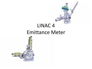
Laser Stripping R&D • Aim at profile + emittance measurement • For testing @ Linac 4 • At least 1 station • Y chamber @ dipole • Establish laser location and optical line path • If there will be no intermediate dump between 1st bend and BI line: • can test only laser stripping and profile meas (no emitt.meas) with a station after PIMS LASER stripping H0 monitor H0 monitor LASER stripping Possible locations H0 monitor L4 BCC - 01 Sep 2011
SOFTWARE • BCT – BPM • Low level completed or well on the way to completion • Need OP GUI development • All will be tested at 3 MeV test stand • SEM grids • Low level and OP GUI done, being used at test stand • BLM • Definition of the memory map • CPU in readout simulation mode • Start development of driver, RT software, etc. • First version of memory map (LINAC4) - end of September L4 BCC - 01 Sep 2011
SPARE L4 BCC - 01 Sep 2011