Download
1 / 31
310 likes | 461 Vues
Interplay of transverse damper and crab cavities W. Hofle BE/RF/FB. Acknowledgements: RF group, G. Arduini , R. de Maria. Outline. Motivation: Scenarios for crab cavities and LHC transverse damper Demonstrated performance of LHC transverse damper in 2010 run

E N D
Interplay of transverse damper and crab cavities W. Hofle BE/RF/FB Acknowledgements: RF group, G. Arduini, R. de Maria W. Hofle, 4th Crab Cavity Workshop
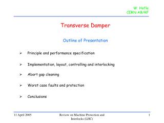
Outline • Motivation: Scenarios for crab cavities and LHC transverse damper • Demonstrated performance of LHC transverse damper in 2010 run • Relevant parameters for mitigation of blow-up related to crab cavity noise • Bunch trains scaling to 7 TeV and possible improvements in transverse damper • Summary and possible studies at the LHC W. Hofle, 4th Crab Cavity Workshop
Motivation • main RF phase error results in time of arrival error in the crab cavity • consequently beam receives dipole kicks in crab cavity • can give rise to coherent motion and emittance increase due to • random kicks, also coherent instabilities (see R. Thomas’ talk) • mitigations: • low RF phase noise (see Philippe Baudrenghien’s talk) • operate transverse feedback to suppress random transverse excitation • and cure coherent instability, • needs operation of transverse feedback with colliding beams • transverse impedance of crab cavities (installed at high b) drives coherent • instabilities that can be cured by transverse damper (see E. Shapochnikova’s talk) • question of whether we can operate the transverse feedback system with • colliding beams is very important to the crab cavity scheme W. Hofle, 4th Crab Cavity Workshop
Scenario for crab cavity • crab cavities made invisible to beam until beams collide • and voltage ramped up by detuning and/or active feedback • crab crossing activated with colliding beams • important for transverse FB: local versus global crab crossing scheme • in global scheme additional issue that the head tail movement • can produce a false signal in the damper pick-ups • this can be mitigated by having damper pick-ups at a multiple • of p phase advance from the IP 1/5 (maybe good for local scheme, too) • local scheme easier as there should be no headtail motion around the ring • in global scheme more difficult to get clean damper pick-up signals • possibility of a headtail feedback (at high frequency) to damp any • residual head tail movement could be considered (global scheme) W. Hofle, 4th Crab Cavity Workshop
Original scenario for LHC damper • use transverse damper for injection oscillation damping • use for tune measurement, PLL as required, as an exciter (abort gap cleaning) • cure coupled bunch instabilities at 450 GeV, • during ramp and at top energy, when required • switched off damper with colliding beams • (stability provided by beam-beam tune spread) but actually used in collision • key point in design is BPM resolution in the micrometer range, • to limit emittance increase • reduce effect of external perturbations on beam (new “hump”) W. Hofle, 4th Crab Cavity Workshop
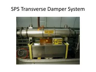
Demonstrated performance of LHC damper 2010 run W. Hofle, 4th Crab Cavity Workshop
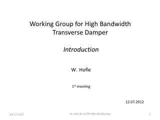
Transverse Damper / Feedback need real-time digital signal processing Match delays: t signal =t beam + MT 0 T0 : beam revolution time M=1: very common -> “One -Turn-Delay” feedback But M>1 also possible phase and delay adjustments Kicker t signal Signal processing gain g t beam D Pick-up 1 Pick-up 2 • damping: of transverse injection oscillations • feedback: curing transverse coupled bunch instabilities • excitation: of transverse oscillations, tune meas. / abort gap cleaning … W. Hofle, 4th Crab Cavity Workshop
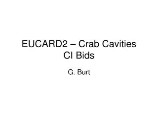
26 kickers 16 wideband amplifiers, i.e. 32 tetrodes in total (RS2048 CJC, 30 kW) H H H V H H H V H V V H V H H V V V V V The LHC Transverse Damping System high power part Naming: #1 to #16 (power team), H1, H2, H3, H4, V1, V2, V3, V4 .B1/B2 > 900 kV integrated kick strength Damper system IP4 Beam 1 Beam 2 damper kicker Wideband amplifier Unit Module Module share common resources, power converters, LL W. Hofle, 4th Crab Cavity Workshop
ADT amplifiers in tunnel point 4 RB44 and RB46 W. Hofle, 4th Crab Cavity Workshop
intensity nomalised bunch position digitised and synchronised (two pick-ups) Overview of signal processing signal processing VME module DSPU (“Damper Loop”) based on 1T-FB module beam position VME module commission in A3 commission in A4 4 x i.e. one system per beam and plane W. Hofle, 4th Crab Cavity Workshop
Time line of LHC damper commissioning 2010 • March set-up of damper BPM front-ends for pilot beam • (later repeated for higher intensity) • 22.04.2010 injection damping beam 2 vertical (V.B2) commissioned • 06.05.2010 40 turns damping time, 125 hours lifetime @450 GeV, V.B2 • 28.05.2010 V.B1 injection damping commissioned • 12.06.2010 H.B1 and H.B2 injection damping commissioned • June commissioning damper in ramp, switch to high intensity • 04.07.2010 first use of feedback with colliding beams • 25.08.2010 set-up for 150 ns bunch trains • 04.09.2010 noise improvements < 2 mm resolution (rms) achieved • 05.09.2010 gain increase for “hump” mitigation, < 20 turns damping time (450 GeV) • 29.10.2010 50 ns set-up (means more bandwidth required from damper) • 18.11.2010 ecloud studies comparing 50 ns and 75 ns bunch spacing W. Hofle, 4th Crab Cavity Workshop
First Damping of Injection errors damper off damper on 22.04.2010 W. Hofle, 4th Crab Cavity Workshop
450 GeV: Initial operation in 2010 - gain Injection damping fill 1268 (August 9, 2010) horizontal plane beam 1 data logged since summer, can be retrieved for analysis W. Hofle, 4th Crab Cavity Workshop
Reducing effect of external perturbations using the transverse feedback “hump control” • the “hump” is an external perturbation (not an instability) seen in LHC • that moves in frequency with time and changes its strength • a high gain is required in the feedback to reduce effects on the beam • narrow range of tune acceptance due to 7 tap FIR filter, but blow-up caused • only around betatron frequency where beam reacts • good performance in terms of S/N of damper pick-up signal processing permits to • run at high gain, is essential, 7 tap filter helps to use both available pick-up • signals to their maximum W. Hofle, 4th Crab Cavity Workshop
Hump mitigation measures We can see the hump and the damper can act on its amplitude -10 dB -10 dB -20 dB -24 dB TFB OFF -10 dB W. Höfle, R. De Maria See talk by G. Arduini @ Evian 2010 W. Hofle, 4th Crab Cavity Workshop
Emittance evolution during tests with strong damping at 450 GeV • following these tests we switched to high gain at 450 GeV with damping times of less than 20 turns to mitigate effect of hump • issue for tune feedback, needed to reduce gain at start of ramp to permit lock • Noise in the TFB pick-up compatible with operation at high gain might see some small blow-up above -10 dB • To be compared with ~1.5-2 mm/h observed for B2-V in the presence of hump OFF 0 dB -20 dB OFF 0 dB -20 dB -10 dB 0 dB -20 dB -6 dB -6 dB -6 dB OFF 0 dB -20 dB -14 dB -4 dB -24 dB -6 dB -10 dB F. Roncarolo reported by G. Arduini @ Evian 2010
Damper gain: 2010 and evolution damper gain damper on, then collapse separation bumps high gain for crab cavity mitigation 20xx injection maintain damping time in ramp (exact function for 2011 to be implemented) strong damping (not used in 2010) squeeze damper not used in 2010 foreseen for 2011 increased damping for hump mitigation 2nd half of 2010 Q-FB on cycle time W. Hofle, 4th Crab Cavity Workshop
Damper tests at 3.5 TeV with different gains tests of August 16, 2010 fill 1287 with colliding beams • Status at that time: • operationally we used a gain setting of -19 dB for all dampers @3.5 TeV with colliding beams; damper switched on before beams are put in collision • different b-functions lead to effectively different damping rates for the two beams and planes, exact damping rates not exactly known • aims of tests: • check the damping at 3.5 TeV with colliding beams (in an end of fill study) • establish damping rate at 3.5 TeV with colliding beams before different gains are applied • method: • use Q-kickers to kick one beam at a time (apply full kick strength) • observe signals in damper (8192 turns), closed loop as function of gain setting W. Hofle, 4th Crab Cavity Workshop
Observation of bunch 1 of both beams in collision collision pattern (observation of bunch 1 in the following): (filling pattern: 25b_16_16_16) Beam 1 bunch 1 Beam 2 bunch 1 IP1 Beam 1 bunch 1 Beam 2 bunch 1 IP5 Beam 1 bunch 1 Beam 2 bunch 8911 IP2 Beam 1 bunch 8941 beam 2 bunch 1 IP8 The two bunches 8941 and 8911 have only two head on collisions. beam-beam tune shift: 3 collisions: x = 3x0.0027 = 0.0081 (at time of experiment: taking 0.82x10¹¹, eavg = 3.66 mm) [ initial at start of fill: x = 0.011 ] W. Hofle, 4th Crab Cavity Workshop
Time domain data (-25 dB and -7 dB gain) horizontal plane, beam 1 -25 dB factor 8 gain increase beating of s and p modes well visible for low damper gain -7 dB data from bunch 1 oscillations (8192 turns), Qkicker used at full strength gain setting: -25 dB and -7 dB, beam 1 kicked, horizontal plane factor 8 gain increase on one beam does not lead to a factor 8 increase of damping beams coupled, gain for damper on other beam was kept constant W. Hofle, 4th Crab Cavity Workshop
Damper used at 3.5 TeV with different gains (horizontal plane) red: beam 2 kicked gain beam 2 damper increased x16 in steps of x2 blue: beam 1 kicked gain beam 1 damper increased x16 in steps of x2 Data from bunch 1 oscillations (8192 turns) gain setting: -25 dB to -1 dB in steps of 6 dB (-19 dB used operational) W. Hofle, 4th Crab Cavity Workshop
Damper used at 3.5 TeV with different gains (vertical plane) red: beam 2 kicked gain beam 2 damper increased x16 in steps of x2 blue: beam 1 kicked gain beam 1 damper increased x16 in steps of x2 Data from bunch 1 oscillations (8192 turns) gain setting: -25 dB to -1 dB in steps of 6 dB (-19 dB used operational) W. Hofle, 4th Crab Cavity Workshop
3.5 TeV: Kicking non colliding bunch with damper on (20 August 2010) 41 ms damping time analysis: U. Wienands used Qkicker to kick the beam and synchronised observation with damper W. Hofle, 4th Crab Cavity Workshop
Damping time versus gain at 3.5 TeV final operation in 2010 analysis U. Wienands W. Hofle, 4th Crab Cavity Workshop
Damping time versus gain at 3.5 TeV analysis U. Wienands suggests practically no or very little damping at zero gain W. Hofle, 4th Crab Cavity Workshop
Damping times achieved and canonical operation in 2010 implementation of trim of gain in physical parameters for 2011 (damping time) set gain to equal values in all planes for all beams for 2011, maintain constant damping time during the ramp (needs update of control system software LSA) 20 to 40 turns damping also tested at 3.5 TeV, but not used during Physics runs W. Hofle, 4th Crab Cavity Workshop
Relevant parameters emittance increase due to external perturbation (like through crab cavity), or “kicker” noise V. Lebedev, V. Parkhomchuk, V. Shiltsev, G. Stupakov, SSCL Pre-print (1993) pick-up signal noise damper gain, measure of fraction of oscillation detected that is corrected run at high gain, limited by PU noise (possibly also stability issues)
From numerical simulations K. Ohmi san et al. (PAC 2007) • for an emittance life-time of 1 day at with an • RF noise characterized by a correlation time and an amplitude (0.22 mrad) • need 0.6% PU resolution (with respect to beam size) • nominal tune spread by beam-beam 7 TeV with nominal emittances (3.75 mm): s = 0.22 mm at b=100 m • 0.6% would be 1.3 mm • corresponds at 3.5 TeV to 1.8 mm achieved already today • some margin from higher beta’s at pick-ups, i.e. beam is actually larger than 0.22 mm • at our pick-ups if b > 100 m, so should be ok today already • working with higher intensities/lower emittances will result in higher • beam - beam tune spread and hence requires proportionally better resolution of PUs • RF noise will determine at what gain we need to run given a certain tune spread • Maximum gain in transverse FB will be limited by stability issues (< 10 turns difficult)
Bunch trains • from noise point of view: RF phase noise filtered by cavity • hence bunch by bunch fluctuations expected to be small • gain roll-off of transverse feedback therefore • not considered an issue for mitigation of transverse excitation • slight time of arrival variation from bunch to bunch due to beam loading in main RF • kicks by CC if CC voltage does not follow this modulation, • result is a different orbit for the bunches • orbit effect is not an issue for damper, but may need quantification • gain roll-off can be an issue for instability damping, E. Shaposhnikova • took conservative approach with respect to damping times (450 GeV) • available from transverse feedback (i.e. take slower rate 20 MHz) W. Hofle, 4th Crab Cavity Workshop
Potential damper S/N improvements towards 7 TeV and needs • beam will be smaller so pick-up resolution normalized to beam size worse • sqrt(2) improvement required to maintain current performance • use of more pick-ups (averaging improves S/N) • higher beta functions at pick-ups (comes for free with CC scheme in collision ?) • electronics improvements / cabling to be quantified (start with this …) W. Hofle, 4th Crab Cavity Workshop
Summary • nominal damping times of transverse feedback system achieved in 2010 • validates assumptions for transverse impedance limits for CC • used with colliding beams at 3.5 TeV with moderate gain setting promising for CC • bunch train operation with 50 ns spacing started 25 ns is goal • scaling to 7 TeV requires some improvement in damper S/N to maintain same • performance as at 3.5 TeV, potential to do so exists • studies with high gain and colliding beams and high gain advised in LHC • to understand better this regime • (quantify emittance blow-up as function of damper noise and gain) • BPM resolution ok for nominal beam • however limit RF noise as we have stability limits for transverse damper • and higher tune spread needs improvement in damper BPM resolution (beta functions ?) W. Hofle, 4th Crab Cavity Workshop