Download
1 / 15
840 likes | 2.86k Vues
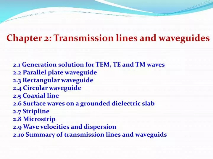
Chapter 2: Transmission lines and waveguides. 2.1 Generation solution for TEM, TE and TM waves 2.2 Parallel plate waveguide 2.3 Rectangular waveguide 2.4 Circular waveguide 2.5 Coaxial line 2.6 Surface waves on a grounded dielectric slab 2.7 Stripline 2.8 Microstrip

E N D
Chapter 2: Transmission lines and waveguides 2.1 Generation solution for TEM, TE and TM waves 2.2 Parallel plate waveguide 2.3 Rectangular waveguide 2.4 Circular waveguide 2.5 Coaxial line 2.6 Surface waves on a grounded dielectric slab 2.7 Stripline 2.8 Microstrip 2.9 Wave velocities and dispersion 2.10 Summary of transmission lines and waveguids
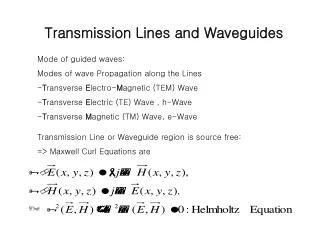
2.1 Generation solution for TEM, TE and TM waves Closed waveguide Two-conductor TL Electromagnetic fields (time harmonic eiωt and propagating along z axis): where e(x,y) and h(x,y) represent the transverse (x,y) E and H components, while ezand hzare the longitudinal E and H components.
In the case of source free, Maxwell’s equations can be written as: With the e-iβz dependence, the above vector equations can be divided into six component equations and then solve the transverse fields in terms of the longitudinal components Ez amd Hz: The cutoff frequency:
(1) TEM waves (Ez = Hz = 0) 0 0 • Propagation constant: (kc = 0, no cutoff) • The Helmholtz equation for Ex: For a e-jz dependence, and the above equation can be simplified Laplace equations, equal to static fields Similarly, • Transverse magnetic field:
0 • Wave impedance: 0 • Note: • Wave impedance, Z • relates transverse field components and is dependent only on the material constant. • For TEM wave • Characteristic impedance of a transmission line, Z0: • relates an incident voltage and current and is a function of the line geometry as well as the material filling the line. • For TEM wave: Z0= V/I (V incident wave voltage I incident wave current)
(2) TE waves (Ez = 0 and Hz0) • The field components can be simplified as: • is a function of frequency and TL/WG structure • Solve Hz from the Helmholtz equation Because , then where . Boundaries conditions will be used to solve the above equation. • TE wave impedance:
(3) TM waves (Hz = 0 and Ez0) • The field components can simplified: • is a function of frequency and TL/WG structure • Solve Ez from Helmholtz equation: Because , then where . Boundaries conditions will be used to solve the above equation. • TE wave impedance:
(4) Attenuation due to dielectric loss Total attenuation constant in TL or WG = c + d. c: due to conductive loss; calculated using the perturbation method; must be evaluated separately for each type. d: due to the dielectric loss; calculated from the propagation constant. Taylor expansion (tan << 1)
2.2 Parallel plate waveguide w >> d (fringing fields and any x variation could be ignored) • Formed from two flat plates or strips • Probably the simplest type of guide • Support TEM, TE and TM modes • Important for practical reasons.
(a) TEM modes (Ez = Hz = 0) • Laplace equation for the electric potential (x,y) for Boundary conditions: • The transverse field , so that we have • Characteristic impedance: • Phase velocity:
(b) TM modes (Hz = 0) • The transverse ez(x,y) satisfies Bn = 0 Boundary conditions: ez(x,y) = 0 at y = 0, d. k > kc traveling wave k = kc ? k < kcevanescent wave Cutoff frequency • Propagation constant: • The field components: Wave impedance: Power flow: (n > 0)
(c) TE modes (Ez = 0) An = 0 The transverse hz(x,y) satisfies And boundary Ex(x,y) = 0 at y = 0, d. where the propagation constant • Wave impedance: • Cutoff frequency :
Parallel plate waveguide TEM TM TE