Download
1 / 47
470 likes | 665 Vues
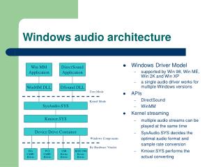
Windows Audio Fidelity Tests And Your Board Design . Kymberly Schmidt Applications Engineer MultiMedia Business Unit Maxim Integrated Products. WLP Device Requirements Premium Mobile, v 3.09. Device Test Manager (DTM). DTM Controller. DTM Studio. Network. System Under Test.

E N D
Windows Audio Fidelity Tests And Your Board Design Kymberly Schmidt Applications Engineer MultiMedia Business Unit Maxim Integrated Products
Device Test Manager (DTM) DTM Controller DTM Studio Network System Under Test Audio Precision Host Audio Precision
Total Harmonic Distortion Plus Noise (THD+N) • A measure of the total non-linearities in a system represented as a percentage of the output signal
Troubleshooting THD+N FailuresTop three contributors • Active Components (CODEC, Amplifier) • Passive Components (Capacitor, Ferrite Bead) • Layout (Grounding)
THD+NActive components • An active component will typically fail at high frequencies if the device is not Windows Vista-compliant Premium Mobile Limit for Line Output
THD+NPassive components • If improperly selected, the Input Coupling Capacitors (CIN) can result in an increase of THD+N at low frequencies Premium Mobile Limit for Line Output X5R 16V X7R 16V
Input Coupling Capacitors • Piezoelectric effect of the input coupling capacitor, CIN, can contribute nonlinearities to the audio signal path (http://www.edn.com/article/CA6430345.html) • Replace CIN with X7R ceramic capacitors with high voltage ratings and measure THD+N performance again
THD+NPassive components • Ferrite beads used for EMI protection at the headphone jack can contribute non-linearities to the audio signal path With ferrite bead Premium Mobile Limit for Line Output
Ferrite Beads • THD+N is dominated by distortion • Replace the ferrite beads in your system with 0W resistors and measure THD+N performance again
Premium Mobile Windows VistaCompliant ferrite beads • The following ferrite beads have been tested in-circuit for THD+N performance and have shown to be premium mobile Windows Vista-compliant TDK………………………..MMZ1608Y601BTA Murata….…………………..BLM18BD601SN1 Taiyo Yuden.……………….LFBK1608HM601
THD+NLayout • CODEC analog ground and audio amplifier ground may not be referenced to the same quiet ground plane • The difference between ground potentials resembles a noise source NON-IDEAL IDEAL
THD+NLayout • Map out IC layout early in the design stage to optimize proximity of analog circuitry NON-IDEAL IDEAL
Full Scale Output Voltage • The maximum output voltage level measured at the output jack
Troubleshooting Full Scale Output Voltage FailuresTop contributor • Attenuation in the signal path
Attenuation In Signal Path • Ensure the CODEC outputs a full scale signal • Ensure the audio amplifier has at least 0dB gain • Ensure any series resistors that may be in headphone output path are not severely attenuating the output voltage
Dynamic Range (DR) With Signal Present • The ratio of the full scale reference level to the weighted RMS noise floor in the presence of a signal • Typical output level is -60dB FS • Expressed in dB
Measuring Dynamic Range (DR) With Signal Present STEP 1: NOMINAL OUTPUT STEP 2: NOISE FLOOR WITH SIGNAL PRESENT
Troubleshooting Dynamic Range (DR) FailuresTop two contributors • Attenuated Output Level • Elevated Noise Floor
Dynamic RangeOutput level • Does the system reproduce a full scale output voltage?
Dynamic RangeNoise • CODEC analog ground and audio amplifier ground may not be referenced to the same quiet ground plane • The difference between ground potentials resembles a noise source NON-IDEAL IDEAL
Dynamic RangeNoise • Noise may be Coupled into the Audio Amplifier Inputs • Gain structure may amplify noise • Output jack ground reference may contribute noise
Crosstalk • Crosstalk measures the amount of signal coupled from one channel to another channel IDEAL NON-IDEAL
Measuring Crosstalk LEFT TO RIGHT RIGHT TO LEFT
Troubleshooting Crosstalk FailuresTop contributor • Layout (IC or PCB) • Capacitive Coupling • Shared, Resistive Ground Return
CrosstalkCapacitive Coupling - causes • High impedance drive of CODEC • Poor separation between stereo amplifier input path
Magnitude Response • A measurement of the output level over a given frequency range referenced to the full scale output level
Measuring Magnitude Response • Sweep a constant-amplitude pure tone through the bandwidth of interest and measure the output level relative to the full scale output level
Troubleshooting Magnitude Response FailuresTop two contributors • System EQ • Passive Components (Coupling Capacitors, Filtering)
Magnitude ResponseSystem EQ • EQ Circuitry may be boosting/suppressing selected frequencies • Disable EQ and repeat measurement
Magnitude ResponseFiltering high frequencies • Passive components around the audio amplifier may be limiting the magnitude response
Magnitude ResponseFiltering low frequencies (Case 1) • Select COUT such that COUT = 1/(2RLfC), where fC is 100Hz and RL is 32W to ensure premium mobile compliance. Be sure to account for the tolerance of COUT C Case Size
Magnitude ResponseFiltering Low Frequencies (Case 2) • Select CIN such that CIN = 1/(2RINfC). Where fC is < 20Hz to ensure premium mobile compliance into a 10kW load 0805 Case Size
Interchannel Phase Delay • The phase difference between stereo outputs • Reported in degrees or microseconds as a function of frequency
Measuring InterchannelPhase Delay • Measure the phase difference of the audio outputs as the frequency is swept between 20Hz and 20kHz • Reported in degrees or microseconds as a function of frequency
Troubleshooting Interchannel Phase Delay Failures Top two contributors • Tolerance of Passives • Digital Domain
Windows Audio Fidelity Debug Tool • THD+N • Crosstalk • Dynamic Range • Frequency Response • Click-and-Pop Select the Audio Specification Your System is Failing:
Additional Resources • WLP Device Requirements: http://www.microsoft.com/whdc/winlogo/hwrequirements.mspx • AES-17 Specification: http://www.aes.org/publications/standards • Audio Precision: http://www.audioprecision.com • Choose Capacitor Types to Optimize PC Sound Quality: http://www.edn.com/article/CA6430345.html • Vista Compliance Troubleshooting Tool: http://www.maxim-ic.com/fidelity-debug-tool