Download
1 / 16
270 likes | 928 Vues
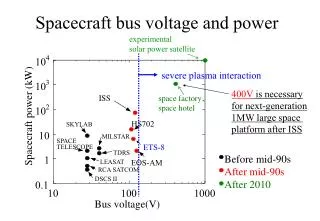
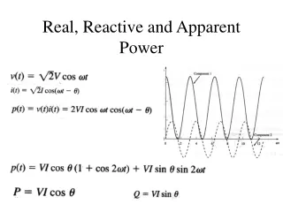
Voltage Stability and Reactive Power Planning. Entergy Transmission Planning Summit New Orleans, LA July 8, 2004. Voltage Profile During Aug 14 th Blackout. Voltages decay to almost 60% and initiates loss of load Slow recovery leads to generators tripping

E N D
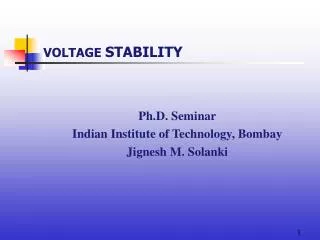
Voltage Stability and Reactive Power Planning Entergy Transmission Planning Summit New Orleans, LA July 8, 2004
Voltage Profile During Aug 14th Blackout • Voltages decay to almost 60% and initiates loss of load • Slow recovery leads to generators tripping • 60% voltage level also observed in 1995 Phoenix-area blackout
East Lake 5 Exciter Operation Exciter trips to manual Exciter trips completely
Power System Outage Task Force • Strengthen Reactive Power and Control Practices in all NERC Regions “Reactive power problem was a significant factor in the August 14 outage, and they were also important elements in the several of the earlier outages” -Quote from the outage report
NERC Recommendations Pertinent to Reactive Power Planning #7. Evaluate reactive power and voltage control practices. • Evaluate the effectiveness of existing reactive power and voltage control standards and how they are being implemented in the NERC regions • Recommend revisions to standards or process improvements to ensure voltage control and stability issues are adequately addressed #14. Improve system modeling data and data exchange practices. • Establish and begin implementing criteria and procedures for validating data used in power flow/stability models by benchmarking model data with actual system performance • Validated data shall be exchanged on an inter-regional basis
What is Voltage Instability/Collapse? • A power system undergoes voltage collapse if post-disturbance voltages are below acceptable limits: • Less than 0.8 PU • voltage collapse may be due to voltage or angular instability • Main factor causing voltage instability is the inability of the power systems to maintain a proper balance of reactive power and voltage control
Voltage Instability/Collapse • The driving force for voltage instability is usually the load. • The possible outcome of voltage instability: • loss of loads • loss of integrity of the power system • Voltage stability timeframe: • Short term/transient voltage instability: 0 - 30 seconds • Motor dynamics/stalling • OEL’s • long-term voltage stability: 1 – 60 minutes • Tap changers/Voltage regulators • OEL’s
Possible Solutions forVoltage Issues • Install/Operate Shunt Capacitor Banks • Add dynamic Shunt Compensation in the form of SVC/STATCOM to mitigate transient voltage dips • Add Series Compensation on transmission lines in the problem area • Implement under-voltage load shed (UVLS) program • Construct transmission/generation facilities
Generator Capability Curve Over-excitation Limit Lagging (Over-excited) 0.8 pf line Stator Winding Heating Limit Normal Excitation (Q = 0, pF = 1) - Per unit MVAR (Q) + MW Leading (Under-excited) Under-excitation Limit Stability Limit
Reactive Power Requirementsfor Generators • The facility should generate reactive power in accordance with the voltage schedule prescribed by the system dispatcher. • Above 230 kV: 1.02 PU • 230 kV: 1.01 PU • 69 kV – 161 kV: 1.00 PU • The facility shall have a reactive power capability to maintain a power factor between 0.95 lagging and 0.97 leading. • Units must be operated with the voltage regulator in auto mode. • Generator may be required to operate at its maximum reactive capability to meet required voltage schedules. • Ensure that adequate reactive reserves are available so that the system can be restored satisfactorily.
Areas of Voltage Stability Concern North Arkansas Mississippi West of the Atchafalaya Basin (WOTAB) Southeast Louisiana Western Region Amite South/DSG
Reactive Power Projects Implemented in Entergy Down Stream of Gypsy (DSG) Area: • 300 MVAR Shunt Capacitor Banks - 2004 • Automatic Under Voltage Load Shedding Program - 2004 • Static exciter at Ninemile 4 Unit - 2004 • 200 MVAR Shunt Capacitor Banks – 2005 • 300 MVAR SVC at Ninemile 230 kV – 2005 Western Region: • Automatic Under Voltage Load Shedding Program – 1998/modified 2004 • Series Compensation on China-Jacinto 230 KV line – 2001 • 300 MVAR SVC at Porter 230 kV – 2005 • Series Compensation on China – Porter 230 kV line - 2005
Summary • The increasing need to operate the transmission system at its maximum safe transfer limit has become a primary concern at most utilities. • Reactive power supply or VAR management is an important ingredient in maintaining healthy power system voltages and facilitating power transfers. • Inadequate reactive power supply was a major factor in most of the recent blackouts.