Download
1 / 23
230 likes | 239 Vues
Experimental test of higher-order LG modes in the 10m Glasgow prototype interferometer. B. Sorazu, P. Fulda, B. Barr, A. Bell, C. Bond, L. Carbone, A. Freise, S. Hild, S. Huttner, J. Macarthur, K. Strain. Introduction – Overview. Motivation of the current work.

E N D
Experimental test of higher-order LG modes in the 10m Glasgow prototype interferometer B. Sorazu, P. Fulda, B. Barr, A. Bell, C. Bond, L. Carbone, A. Freise, S. Hild, S. Huttner, J. Macarthur, K. Strain
Introduction – Overview • Motivation of the current work. • Presenting Glasgow interferometric GW detector 10 m prototype. • LG33 mode generation on the prototype’s input laser bench. • Preliminary results. • Conclusions.
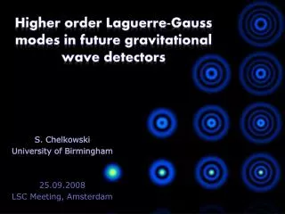
Motivations Higher-order LG mode beams are being considered for implementation on future generations of GW interferometers. LG modes are expected to considerably reduce thermal noise (both mirror coating and substrate Brownian noise) in comparison with TEM00 beams [1,2,3]. Results from simulation work and benchtop experiments [3,4] on higher order LG mode interferometry encourage us to take the next step; testing in an environment similar to an interferometric GW detector. [1] B. Mours et al. Thermal noise reduction in interferometric gravitational wave antennas: using high order TEM modes, CQG 23, 5777, 2006 [2] J.-Y. Vinet On special optical modes and thermal issues in advanced gravitational wave interferometric detectors, Living Revs. Rel. 12(5), 2009 [3] S. Chelkowski et al. Prospects of higher-order Laguerre- Gauss modes in future gravitational wave detectors, Physical Review D 79,122002, 2009 [4] P. Fulda et al.Experimental demonstration of higher-order Laguerre-Gauss mode interferometry, Physical Review D 82, 012002, 2010
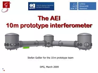
The Glasgow 10m Prototype Interferometer • GEO-like infrastructure: • Similar vacuum systems • Triple stage GEO-suspensions • Same local control • Ideal test bed for advanced interferometry concepts (e.g. Signal recycling, optical spring). • Fast turn around for rapid, small-scale tests • Timely validation of various innovative technologies (e.g. higher order LG modes, diffractive interferometry) • Excellent training for students and Postdocs
The Glasgow 10m Prototype Interferometer Maximise potential of the Glasgow prototype by carrying out several strands of experiments in parallel: Direct measurement of thermal noise 3-mirror coupled cavity systems: Control strategies • S.Huttneret al.Novel sensing and control schemes for a three-mirror coupled cavity, CQG 24, 3825, 2007. • B. Barret al. Optical modulation techniques for length sensing and control of optical cavities,Appl. Opt. 46, 2007. • S. H. Huttneret al.Techniques in the optimization of length sensing and control systems for a three-mirror coupled cavity, CQG 25, 235003, 2008. Radiation pressure experiments Frequency reference for TN experiment Thermal Noise Reduction Cavity
The Glasgow 10m Prototype Interferometer Thermal noise reduction cavity systems: Diffractive grating as cavity incoupler • M.Edgaret al. Experimental demonstration of a suspended diffractively coupled optical cavity, Opt. Lett. 34, pp. 3184-3186, 2009. • M.Edgaret al. Experimental demonstration of a suspended, diffractively coupled Fabry–Perot cavity, CQG 27, 084029, 2010. • B. Barr et al.Translational, rotational and vibrational coupling into phase in diffractively- coupled optical cavities, accepted for publication Optics Letters. Waveguide mirror (First realization of a waveguide suspended cavity with a finesse of 800) • D. Friedrich et al. Waveguide grating mirror in a fully suspended 10 m cavity, accepted for pub. Optics Exp. http://arxiv.org/abs/1104.2780 Thermal Noise Reduction Cavity Waveguide Cavity
The Glasgow 10m Prototype Interferometer Thermal noise reduction cavity systems: Diffractive grating as cavity incoupler • M.Edgaret al. Experimental demonstration of a suspended diffractively coupled optical cavity, Opt. Lett. 34, pp. 3184-3186, 2009. • M.Edgaret al. Experimental demonstration of a suspended, diffractively coupled Fabry–Perot cavity • CQG 27, 084029, 2010. • B. Barr et al.Translational, rotational and vibrational coupling into phase in diffractively- coupled optical cavities, accepted for publication Optics Letters. Waveguide mirror (First realization of a waveguide suspended cavity with a finesse of 800) • D. Friedrich et al. Waveguide grating mirror in a fully suspended 10 m cavity, accepted for pub. Optics Exp. http://arxiv.org/abs/1104.2780 Higher order LG modes Thermal Noise Reduction Cavity
LG33 in the Glasgow 10m GW detector prototype • Outcome of the successful ongoing collaboration with the University of Birmingham. • Main aims of the experiment: • Gain some experience in how to handle high order LG modes in a prototype environment. • Study of interferometer control signals with high order LG modes. • Locking a single 10m cavity on high order LG modes. • Investigating effects from mode-degeneracy (see talk by C. Bond at Advanced det. Technologies session Amaldi 9 (2011), R. Adhikari at GWADW 2010 at Kyoto)
Some notes about mode - degeneracy • Different mode orders are separated in cavities because the round trip Gouy phase for a mode = (order + 1) * Gouy phase • Modes of the same order have the same round trip Gouy phase, therefore aren't separated in cavities. • Coupling into other modes of the same order will lead, potentially, to different combinations of modes in the different arm cavities. Circulating Power • In real cavities the modes are not perfectly degenerated, they have slightly different resonant frequencies due to experiencing a different average mirror curvature or cavity length. • This leads to error signals with multiple zero crossings making it difficult to lock stably to one of this ‘pseudo’ degenerated modes. • Here we show an example of such ‘pseudo’ degeneracy on a 3 mirror mode cleaner with astigmatism. PDH Error Signal However, first simulations with mirror maps have shown that the expected range of the frequency splitting is much smaller than our 10m cavity line width. Therefore we do not expect to observe this phenomenon. Cavity tuning [deg]
LG33 generation – Input Laserbench • LG33 generation optics have four purposes: • Generation of a LG33 mode from a laser emitted TEM00 mode. This is done with a diffractive optical element (DOE). • Purification of the generated LG33 mode. By means of a linear modecleaner (LMC); 23 cm long planoconcave cavity with a finesse of 172 and 714MHz FSR. • Adding phase modulation onto the beam for cavity lock. Through an EOM. • Ensuring a good alignment of the prototype’s 10m cavity for the LG33 beam. For this we have a pick off path of the TEM00 that avoids the DOE and passes the LMC. TEM00 and LG33 share same eigenmode inside the LMC.
LG33 degradation through the Glasgow prototype After 1st MM lens After LMC Max. residual 0.18 Max. residual 0.30 Cavity misaligned End Mirror - transmission After 4 EOM crystals and FI Max. residual 0.33 Max. residual 0.50
Results – Locking onto high order LG modes 1st order • Good cavity alignment as shown by the visibility of TEM00 mode resonance with respect to higher order one. 0th order • Still see reasonable resonances but so far cavity power buildup is a factor 5 less. • However, still the desired mode-order is dominant.
Results – High order modes resonance freq. split • The resonance peak of the TEM00 mode shows a single peak...as expected.
Results – High order modes resonance freq. split • Scanning several FSR for LG33 mode
Control signals (errorsignal, feedback signal and transmitted power) and cavity mode shape when locked onto the highest peak. During the video we intentionally gave longitudinal kicks to the mirrors to lock to different modes within the peak. Results – High order modes resonance freq. split
Recording the mode shape of the transmitted beam with a high speed camera during the transition between the peaks of the frequency split modes. Plans for investigation of modes resonance freq. split • HS IR cameras are expensive so we built our own • A commercial Casio Exilim... was chosen • The camera was completely disassembled in order to remove the IR filter on the CCD • The camera was assembled back and tested that it worked fine
The HS camera provided a nice view of the multipeak resonance features. In these results we had cavity aligned to the order 7 mode, but freq. split resonance still there. Plans for investigation of modes resonance freq. split
The previous video was accompanied with a synchronized high resolution trace of the transmission PD DC level. We zoom onto one of the freq. split resonance features and attach video screenshots associated to each of the freq. splits: Plans for investigation of modes resonance freq. split • The video seems to confirm that the observed freq. splitting of the resonant peak is due to pseudo-degenerate modes.
Use a second auxiliary laser at freq. 1 FSR away from main laser. Freq. difference between laser stabilized with PLL servo. Lock cavity to aux. laser and modulate PLL LO to scan LG33 freq. relative to the locking laser. Plans for investigation of modes resonance freq. split Technique suggested by Koji Arai et al. Precise measurement of long. and transv. mode spacings of an optical cavity using an auxiliary laser, G080467, 2008.
Conclusions Set up an experiment to test LG33 mode in a suspended 10m cavity featuring a nominal finesse of 600 (close to Advanced Detector config). Found it relatively easy to lock to order 9 modes. After some preliminary experimental test it may seem that the same setup that was adequate for stable locking to the TEM00 mode was not found to be adequate for the locking of the cavity to the LG33 mode. Further measurements will be carried out to allow confirmation. => So far no quantitative statement can be made about the expected mode degeneracy and associated problems Observation of multiples peaks around the order-9 resonance. So far unexplained. Simulations with real mirror imperfections and further measurements in progress. Outlook: Different reflectivity mirrors are available to investigate how unexplained effects scale with different cavity finesse.