Download
1 / 6
60 likes | 143 Vues
Direct Channel Eye Pattern Correction in High Speed Links By Steve Chacko & Ellis Goldberg Furaxa Inc. Closed eye. Opened eye. Direct Channel Eye Pattern Correction.

E N D
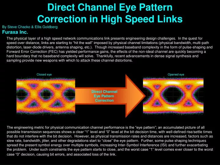
Direct Channel Eye Pattern Correction in High Speed Links By Steve Chacko & Ellis Goldberg Furaxa Inc. Closed eye Opened eye Direct ChannelEye Pattern Correction The physical layer of a high speed network communications link presents engineering design challenges. In the quest for speed over distance, links are starting to “hit the wall” imposed by physical channel limitations (physical bandwidth, multi-path distortion, laser-diode drivers, antenna shaping, etc.). Though increased baseband complexity in the form of pulse-shaping and Forward Error Correction (FEC) has yielded performance gains, the effects of the non-ideal channel are quickly becoming a hard boundary that no baseband complexity will solve. Thankfully, recent advancements in dense signal synthesis and sampling provide new weapons with which to attack these channel distortions. The engineering metric for physical communication channel performance is the “eye pattern”; an accumulated picture of all possible transmission sequences shows a clear “1” level and “0” level at the bit-decision time, with well-defined rise/settle times that do not interfere with the bit decision. However, as physical transmission rates and distances are increased, factors such as slew rate, bandwidth, jitter, and other degradations start to “close” the eye pattern. Further, some pulse shaping techniques spread the present symbol energy over multiple symbols, increasing Inter-Symbol Interference (ISI) and further exacerbating the problem. Under such constraints the eye pattern starts to close, and the worst case “1” level comes ever closer to the worst case “0” decision, causing bit errors, and associated loss of the link.
Eye Pattern closes with increases in bit rates and transmission distance Distance Speed Source: http://grouper.ieee.org/groups/802/3/ae/public/mar00/goergen_1_0300.pdf
Direct Channel Eye Pattern Correction Recent advances in arrayable ultra-fast pulse and sampling aperture generation make it possible to mitigate eye pattern closure with embedded link monitoring and correction. Direct Channel Correction is now possible, even at data rates of 40Gb/s. The pulse and sampling aperture generation technology must be capable of speeds at least 2-3 times greater than the data rate, to allow reliable sub-symbol sampling and synthesis. Oversampling 12 Gb/s by ~4X 1 clock = 83.3psec The closed eye pattern means that there is a high probability that a 1 will be mistaken for a zero or a zero for a one. By over sampling at 4 times the clock rate enough one/zero data is captured to determine the true bit value. Embedded DSP hardware makes that determination. 1 sample every 20psec
Direct Channel Eye Pattern Correction Technique Rx side Closed eye Tapped delay line 20psec taps Libove Sampler Libove Sampler Libove Sampler Libove Sampler Single Shot Sampling Array The technique makes use of a high speed sampling array, lower speed parallel processing hardware, and a high speed pulser array. Sampling, analysis, correction, and resynthesis are accomplished in an elegant, low-cost solution. Such a system allows continuous link monitoring, detection, and correction at both transmit and receive terminals. ADC/ Sample & Hold ADC/ Sample & Hold ADC/ Sample & Hold ADC/ Sample & Hold Lower speed processing Digital Signal Processing Hardware High SpeedPulser Array Libove Pulser Libove Pulser Libove Pulser Libove Pulser Opened eye Tapped delay line
Direct Channel Eye Pattern Correction Technique This “closed loop” flexible system enables full TDT/TDR capability to be embedded at the NIC physical level yielding dramatic increases in overall ink performance Optical to electrical or Electrical to electrical Rx side Single Shot Sampling Array By monitoring the reflected input on the RX side the DSP determines the appropriate correction to make to the shaped output pulses to pre-correct the TX signal for optimal transmission distance and reliability. Decoder Encoder Deserializer Serializer Digital Signal Processing Hardware Libove Pulser Libove Pulser Libove Pulser Libove Pulser Transmit Array Tx side Tapped delay line 10 Gb/s Ethernet transmission might be oversampled at 50 GS/s by a “single-shot” sampling array. These samples are then digitized and passed to a lower speed digital processor for spectral analysis and correction algorithms calculation to create desired pre-corrected waveform for the corresponding Tx array. Using this approach, every Tx-Rx pair in the network can be individually monitored and dynamically optimized. .
Ready to move outside the Analog Digital Boundary? • The demand for speed over distance requires addressing some difficult channel non-idealities. The historical answer to this problem, throwing more complexity into the digital signal processing, is quickly reaching a state of decreasing marginal returns. Armed with recent advances in synthesis and sampling technology, engineers who are willing to move outside the Analog Digital Boundary will likely make the next great strides in communications system design. • The Libove Pulser Sampler from Furaxa is ideally suited for this application: • Highly arrayable, stable architecture • Reliable and consistent operation • Sample apertures & Pulse generation as short as 10 picoseconds • Repetition rates to 8GHz • Excellent linearity • Inexpensive monolithic design, small footprint Contact Furaxa at 925 253 2969 or sales@furaxa.comto discuss how we might help you. www.furaxa.com