Download
1 / 47
480 likes | 503 Vues
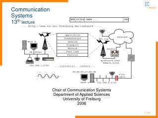
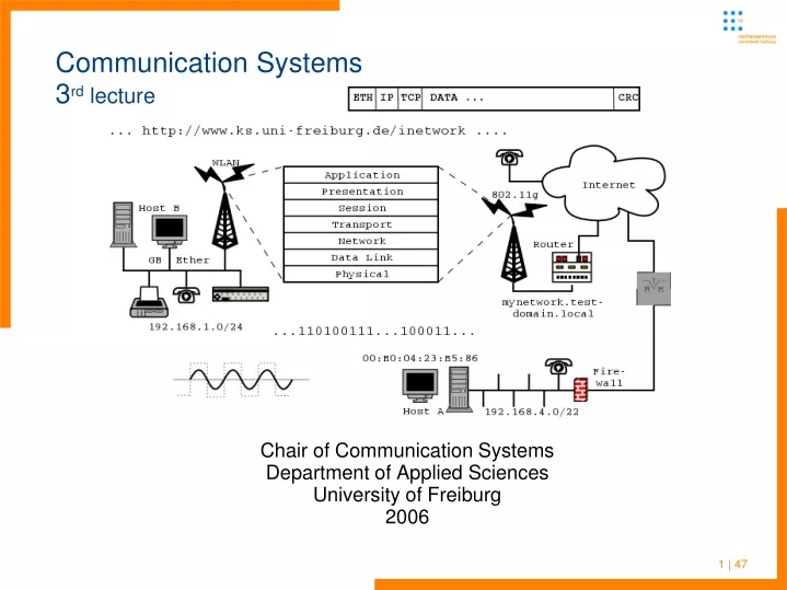
Chair of Communication Systems Department of Applied Sciences University of Freiburg 2006. Communication Systems 3 rd lecture. 1 | 47. Communication Systems Last lecture. Message segmentation in packet switched networks advantage over message switching

E N D
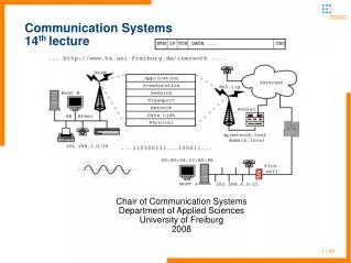
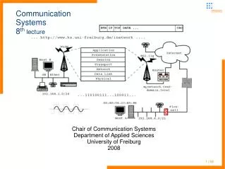
Chair of Communication Systems Department of Applied Sciences University of Freiburg 2006 Communication Systems3rd lecture 1 | 47
Communication SystemsLast lecture • Message segmentation in packet switched networks advantage over message switching • Different types of packet forwarding/routing in • Datagram networks (Internet, ...) • Virtual circuit networks (ISDN, ATM, ...) • Got taxonomy of different network types (circuit and packet switching with respective subtypes) • Requirements for communication between so called end systems • Network access, different types (home, company, mobile) • depending on requirements of end users 2 | 47
Communication SystemsLast lecture • Physical representation of digital bit streams all kinds of electromagnetic waves (electromagnetic spectrum) • Encoding, decoding of data for transport over different types of media • Physical parameters: frequency, wavelength, (effective) bandwidth, Nyquest formula for max. bandwidth of given medium • Copper wire (single twisted pair for telephone, higher quality for ethernet, fiber optics), “air” (mobile phones, satellite links, WLAN, ...) • Guided and unguided media, propagation delay (speed of light) 3 | 47
Communication Systemsplan for this lecture • Standards and network layering models • OSI and IP • Need of an universal service • IP as layer 3 network protocol • Start with look at IP header 4 | 47
Communication Systemsnetwork layer models • Talked of some base concepts of data communication and bit transportation • But how to do that in an ordered and general way? • A structured composition of networks is needed for data communication of very different machines and operating systems • There are several of these models, the ISO/OSI layering model is one of them • ISO: International Standards Organization • OSI: Open Systems Interconnect • Reference model for implementation of network architectures 5 | 47
Communication Systemsnetwork layer models • OSI: “Academic model” which shows seven layers • It helps to illustrate and implement the core function of networks, but no real networking architecture is modeled after it • More practical is the TCP/IP layering model with fewer layers • In general: • Layering breaks down very complex tasks into simpler ones • Implementation details in one layer are abstracted away from the others • But: Can introduce overhead and need for intentional violation of layering concepts 6 | 47
Communication Systemsnetwork layer models - “academic” OSI model 7 | 47
TCP/IP Layers Application Layer Transportation Layer Internet Layer Physical Layer Communication Systemscomparison of OSI and TCP/IP layers OSI Layers • Application Layer • Presentation Layer • Session Layer • Transportation Layer • Network Layer • Data Link Layer • Physical Layer 8 | 47
Communication Systemscomparison of OSI and TCP/IP layers OSI in comparison to TCP/IP (developed by ARPA) 9 | 47
Communication Systemswhy talking about layer models? • There are quite a few layering models with different levels of abstraction • Some models reduce the OSI to five layers and move session and presentation into application (Tanenbaum) • Some real live employment of networks will show that some layers have to be split up • Tunneling of protocols and protocol stacks through other layers or protocols would introduce rather complex models, tunneling can occur on various layers • ethernet in ATM • IP and others over PPP • IP over DNS – useful for many hotspots with blocked general IP but open DNS, IP over HTTP/WAP ... 10 | 47
Communication Systemswhy talking about layer models? Cont. • Network layering is not a strictly defined issue, you will find sublayers, e.g. in Mobile networks like GSM or 802.11 • Much combinations of layers and protocols are possible (and used - “tunneling of stacks within layers”) 11 | 47
Communication Systemswhy talking about layer models? Cont. • Further on the lecture will embroider some of the presented layers and ignore others • But layering will help to understand complex problems and split them into manageable units – general concept of computer science • The next part of this lecture will deal with the network layer (present in nearly every network model) • The most important representative of this layer is the internet protocol (IP) • IP used in every host-to-host connection • Many physical layer implementations • Many applications operating over IP • So we will start with IP now ... 12 | 47
Communication Systemsuniversal service connecting networks • We introduced some different kinds of physical networks • Modem, ISDN, DSL for connection of individuals • Technologies like Ethernet (over copper and fiber optics) • Wireless networks, ... • Many implementations for different networking purposes • Wide Area Networks (WAN) which may span countries (e.g. DFN for Germany or GEANT for Europe) or even continents; connecting infrastructure components like routers not end user machinery • Local Area Networks (LAN) which implemented within buildings, mostly bridging only short distances with many hosts connected • In the past distinction of networks by bandwidth offered 13 | 47
Communication Systemsuniversal service connecting networks • Each type of network structure may require or be implemented with different low level protocols 14 | 47
Communication Systemsconnecting networks • DSL as an example for dedicated point-to-point connection over a two wire copper cable with a length up to 6km • Ethernet – packet orientated LAN protocol • Multilink (broadcast) network with no dedicated point-to-point connections • Different speeds over copper wire, coaxial cable and fiber optics • ATM – connection orientated LAN and WAN protocol • Virtual ptp connection through virtual channels and pathes • Modem, ISDN for WAN, FDDI, TokenRing, ... for LAN • Wireless links on GPRS, HSCSD, UMTS, WLAN, ... 15 | 47
Communication Systemsconnecting networks cont. • Intermediate protocol with unified addressing scheme is needed 16 | 47
Communication Systemsconnecting networks • Universal protocol needed is implemented in the network layer • Network layer is third layer in OSI model • Physical layer (first layer) implements the real bit connection over different media (e.g. Twisted pair or optical fiber with Ethernet or “air” for UMTS or GSM) • Data Link Layer contains higher level protocols of Ethernet, GSM, UMTS, ... not discussed in depth in this lecture • Each layer adds its header to a packet • Needed for packet handling and routing 17 | 47
Communication Systemsconnecting networks • Helper protocols needed during packet processing • Inform senders on congestion or lost packets • Map different layers addresses on each other 18 | 47
Communication Systemsfunctions of an universal service • Define unified addressing scheme which is hardware/software independent • Realize datagram delivery between networks • Hosts – end systems as defined in first lecture • Routers touch two or more networks, forward network-layer datagrams between them (routers use layer 3) • Routers execute routing protocols to learn how to reach destinations • Universal service protocol should be an open standard without fees and licenses to be paid to get acceptance • May implement/use helper protocols (ARP and ICMP for IP, introduced in practical or theoretical exercises) 19 | 47
Communication Systemsissues of an universal service • Network layer provides end-to-end delivery (routing) • Provides consistent datagram abstraction: • best-effort delivery • no error detection on data • consistent maximum datagram size • consistent global addressing scheme • Link layer (second in OSI) networks provides delivery within the same network • Typically includes its own addressing format (e.g. Ethernet), and maximum frame size (MTU) 20 | 47
Communication Systemsinternet protocol details • IP version 4 is current • IPv6 forthcoming • Solution to the address space exhaustion of IPv4 • Predicted for a while, but limit not reached yet • Solutions for preserving numbers in IPv4 (masquerading, private networks ...) • At the moment nobody knows when it will be used other then in backbone structures • 3G/UMTS mobile telephone market may push IPv6 • Defined for a while – we will spend a dedicated lecture on it 21 | 47
Communication Systemsinternet protocol details • Protocol header includes: • Version field • Source and Destination addresses • Lengths (header, options, data) • Header checksum • Fragmentation control • TTL, and TOS info • But TOS info often ignored • Easy changeable along the path (so what for?) 22 | 47
Communication Systemsinternet protocol header details • Version field (4 standard, 5 STII, 6 next gen IP) and IP header length are of 4 byte • IP header normally consists of 20Byte, with options more • Length needed to compute where next header starts 23 | 47
Communication Systemsinternet protocol header details cont. • IP options may sum up to 40Byte • Total length field is 16bit, maximum packet length therefore may not exceed 64kByte • Minimum is 20Byte (just the IP header) • MTU of standard physical networks much smaller (e.g. 1,5kByte) • 16bit identification field for fragments • Set for every packet by original sender of datagram • Sender can not know if fragmentation may occur • Initial message segmentation may not small enough • Copied into each datagram during fragmentation 24 | 47
Communication Systemsinternet protocol header – fragmentation • Content of 16bit identification field is computed by sender • Different OS use different computing schemes (tool “nmap” in practical course) • Might give away information on OS, internal network structure • Masqueraded machines could be identified by their fragmentation IDs • Counter on every machine will have different values (amount of traffic generated, computing scheme ...) • A private network may give more information away than intended 25 | 47
Communication Systemsinternet protocol header – fragmentation • Flags for fragmentation control • MF: more fragments (follow) • DF: dont fragment (some protocol implementation like DHCP in Boot-ROMs are not able to reassemble fragmented packets), feature may be used for MTU path discovery (increment packet size until ICMP error message is generated because auf fragmentation need) • Fragmentation offset • Offset of this fragment into the original datagram • Zero if no fragmentation used • why offset and not fragment number? - if further fragmentation is needed 26 | 47
Communication Systemsip header – protocol field • Protocol field – the payload with headers removed is passed to a higher layer in the networking stack -> where? • There are different transportation layer protocols for different purposes • 1: ICMP – discussed later this lecture • 6: TCP – Transmission Control Protocol • 17: UDP - User Datagram Protocol • 50: ESP – Encapsulating Security Payload • 51: AH - Authentication Header • All protocol names and corresponding numbers are listed in (/etc/)protocols file (linux operating system – see practical course) 27 | 47
Communication Systemsip header – protocol field • In general: each layer has to provide the information which upper layer should process a given type of packets • Each protocol adds its own header to the packet 28 | 47
Communication Systemsip header – address fields • Source address • 32 bit length defines the IP address space • Should never be changed through ordinary routing (there are some exceptions like network address translation (NAT)) • Protocol does not force authentication of source (often enforced by modern routers now) • Destination address • 32 bit length defines the IP address space • Should never be changed through ordinary routing • Changes when source routing used (realised through IP option header) 29 | 47
Communication Systemsinternet protocol – header details • Source routing • Special handling for particular datagrams, sometimes don't take router's "fast path" • Rarely used, but the more common are: Loose Source Routing, Strict Source Routing and Record Route • Timestamp • Must copied on fragmentation • More on routing little bit later on 30 | 47
Communication Systemsip – fragmentation of packets • Gave short introduction already, but ... • Adapting datagram size one of the most important tasks of the internetworking protocol: • IP datagrams itself cannot exceed 64kbyte • Lower protocol levels report MTU (max. transfer unit) • Linux loopback 16384byte • Ethernet frames offer max. payload of 1500byte • ATM offers 48byte • slow modem-ppp connections 296byte packet length • The tool ifconfig or ip (first practical course) reports MTU of each interface 31 | 47
Communication Systemsip – fragmentation of packets • Fragmentation & Reassembly • divide network-layer datagram into multiple link-layer units, all have to be equal or smaller then link MTU size • Further fragmentation may be needed if MTU is decreased along the path again • Sometimes it is more clever to set MTU smaller at source to avoid later fragmentation • Reconstruct datagram at final station • Each fragment otherwise acts as a complete, routeable datagram • Datagrams are identified by the (source, destination, identification) triple • Concept of fragmentation changes with IP v6 32 | 47
Communication Systemsip – fragmentation of packets cont. • If fragmented, identification triple is copied into each resulting packet • Also contains (offset, length, more) triple • more - boolean indicates is last fragment • offset - relative to original datagram • Relating fragments to original datagram provides: • Tolerance to re-ordering and duplication • Ability to fragment fragments (!) 33 | 47
Communication Systemsip – fragmentation of packets cont. • IP fragments are re-assembled at final destination before datagram is passed up to transport layer • Routers do not reassemble fragmented datagrams • Allows for independent routing of fragments • Reduces complexity (need for CPU and memory) in routers • Problems with fragmenting: • Loss of 1 or more fragments implies loss of datagram at the IP layer • IP is best effort, provides no retransmission, will time-out if frag(s) appear to be lost • May be interesting for DoS attacks 34 | 47
Communication Systemsip – fragmentation of packets cont. • Avoid fragmentation through computing path MTU • Problems if path changes (dynamic routing) and new path has smaller MTU along its way • Adapting size of packets in the source machine according to the “minimum MTU”: Path MTU Discovery • IP v6 uses MTU discovery and assumes standard minimum MTU • If datagram size is smaller then MTU, no fragmentation needed • How to do this? • Probe network for largest size that will fit • If possible, have network tell us this size • Operates through ICMP messaging (presented later on) 35 | 47
Communication Systemsip – addressing scheme • We saw that IP packet header reserved two 32 bit fields for source and destination address • For computation for delivery decisions the binary form is used only • Programs and operating systems implementing IP automatically convert the addresses between the two representations • IP addresses are topologically sensitive • Interfaces on same network share prefix • Prefix is assigned via ISP/local network administrator • 32-bit globally unique 36 | 47
Communication Systemsip – addressing scheme cont. • Address is split into two virtual parts: network and host part • See later how division is done • For better reading the binary representation could be split into four octets, which are transferred into the decimal system 37 | 47
Communication Systemsip – addressing scheme cont. • The early IP standard defined five address classes: A, B, C, D and E • An IP address should be selfexplanatory, it should countain information on the networking sub structures • History by now • In this view the address consists of a pattern of high order bits, which shows their class, the network and the host component • Machines in the same network share a common prefix (the class definition and network component of IP) and must have unique suffix (the host component of IP) 38 | 47
Communication Systemsip – (historic) address classes 39 | 47
Communication Systemsip – address classes cont. • Class A: (high order bits: 0) • Large Organizations, few nets (127), huge number of hosts (16.7 million) • Address range in decimal notation 0.0.0.0 – 127.255.255.255 • Class B: (high order bits: 10) • Medium sized organizations and firms, e.g. University of Freiburg, some nets (16,384) and large number of hosts (65,536) • Address range 128.0.0.0 – 191.255.255.255 • Class C: (high order bits: 110) • Small organizations and firms, relatively large number of nets (2,097,152) with a small number of hosts per net (256) • Ranging from 192.0.0.0 – 223.255.255.255 40 | 47
Communication Systemsip – address classes cont. • Class D: (high order bits: 1110) • Multicast addresses, but service are not very often used • Address range 224.0.0.0 – 239.255.255.255 • Class E: (high order bits: 1111) • Declared for experimental use only • Address range 240.0.0.0 – 255.255.255.255 • Theoretical address space is 4,294,967,296 (seems a lot :-) - but population on earth is higher by now) • But the address space usable for the “internet” is limited to addresses from 1.X.Y.Z up to 223.X.Y.Z 41 | 47
Communication Systemsip – addressing scheme • But you will loose some more addresses: • Special addresses like: • 0.0.0.0 defines the default route (explained later, route for the “whole internet”) or the start address of a host searching for a dynamically provided IP • 255.255.255.255 local broadcast address (and destination for hosts seeking an IP via DHCP) • 127.0.0.0 loop back network address (you will need only one address within this range and use typically 127.0.0.1). This address is used by every host implementing IP (software using IP for communication is usable without internet connection) 42 | 47
Communication Systemsip – “private” addresses • Addresses reserved for “private” use – many organizations, enterprises, flat-sharing communities need IP communication for their applications without or restricted internet access • 10.0.0.0 – 10.255.255.255 (within the class A range) • 172.16.0.0 – 172.31.255.255 (16 class B networks) • 192.168.0.0 – 192.168.255.255 (65,536 class C networks) • University WLAN, private LAN is using 10.X.Y.Z addresses • Addresses within these ranges should be discarded on internet routers • Address classifying helped in the beginning for faster network decicion computation, routers had limited memory and cpu power 43 | 47
Communication Systemsip addressing • For addressing whole subnets or addressing all hosts within a given subnet (possibility depends on the underlying physical network) special IP addresses are introduced • Network number is the smallest IP address in a given (sub)network. it does not address a single machine and may not assigned to a host. It is used with routing tables (explained later in detail) • Broadcast address is the largest possible IP in a network. It should be not assigned to a host, but is the possibility to reach all hosts in a network with just one packet • If we use the example class B address 172.31.5.200, this machine is a member of a network with the network number 172.31.0.0 and a broadcast address 172.31.255.255 44 | 47
Communication Systemsip subnetting • Networks with huge number of hosts could be split into subnets for better administration and considerations on physical topology and global spanning net • The example class B network 172.16 with 65536 host ip numbers in it, allows 256 subnetworks with 256 hosts in it if split on the byte boundary • But: The resulting 256 “class C networks” have the same high order bit like the original class B network 45 | 47
Communication Systemsliterature list • Network Layering: • Kurose & Ross: Computer Networking (3rd), Section 1.7 • Tanenbaum: Computer Networks (4th), Section 1.4 • Internet Protocol 4 • Kurose & Ross: Computer Networking (3rd), Section 4.4.1 • Stevens: TCP/IP Illustrated Vol. 1, Section 3.2 • Tanenbaum: Computer Networks (4th), Section 5.5.7, 5.6.1 • IP Addressing • Kurose & Ross: Computer Networking (3rd): Section 4.4.2 • Tanenbaum: Computer Networks (4th): Section 5.6.2 • Stevens: TCP/IP Illustrated Vol.1, Section 1.4, Section 3.4 46 | 47
Communication Systemsliterature list (cont.) • ARP • Kurose & Ross: Computer Networking (3rd): Section 5.4.1, Section 5.4.2 • Tanenbaum: Computer Networks, 4th edition: Section 5.6.3 • Stevens, TCP/IP Illustrated Vol. 1: Section 4.6, Section 5 • ICMP • Stevens, TCP/IP Illustrated Vol. 1: Section 6, Section 9.3--9.6 • Tanenbaum, Computer Networks, 4th edition: Section 5.6.3 • DHCP • Kurose & Ross, Computer Networking (3rd): Section 5.4.3 • http://www.ks.uni-freiburg.de/php_termindetails.php?id=39 47 | 47