Download
1 / 15
160 likes | 298 Vues
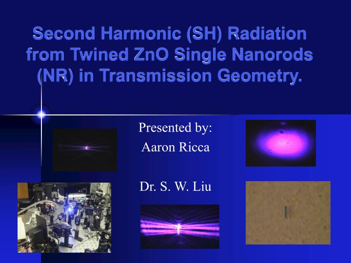
Second Harmonic (SH) Radiation from Twined ZnO Single Nanorods (NR) in Transmission Geometry. Presented by: Aaron Ricca Dr. S. W. Liu. Outline. Backround on SHG and ZnO Experimental Setup Experimental Procedure Results. Second Harmonic Generation (SHG) and ZnO.

E N D
Second Harmonic (SH) Radiation from Twined ZnO Single Nanorods (NR) in Transmission Geometry. Presented by: Aaron Ricca Dr. S. W. Liu
Outline Backround on SHG and ZnO Experimental Setup Experimental Procedure Results
Second Harmonic Generation (SHG) and ZnO It’s a nonlinear optical (NLO) process that, when discovered, started research in NLO materials Photons pass through NLO material and constructively interfere to form a photon of twice the frequency, and energy, and half the wavelength Much research done on ZnO in other areas because very stable, i.e. Peizoelectric and pyroelectric effects, UV and electron field emission, electrical conductivity… but not much in SGH of ZnO
PMT Spectrometer L CCD IR P Camera FM OB BF PC S LF L Lock-in /2 Lock-in BS BBO BF PMT CH 2 KHz Ti:Sapphire 82 MHz,100fs M Experimental Setup The schematic of the experimental setup. PMT: photo-multiplier tube; CCD: charge coupled device cooled by liquid nitrogen; BBO: BBO nonlinear crystal; BS: beam splitter; LF: long-pass filter; BF: band-pass filter; CH: chopper operating at 2 KHz; /2: half-wave plate; P: Glan polarizer; L: lens; IR: iris diaphragm; OB: removable objective; M: mirror; FM: flipper mirror; PC: computer; S: sample. BBO used to provide a reference to remove laser intensity fluctuations Laser wavelength = 810 nm
Finding the Nanorod Extremely Difficult to locate, then re-locate if needed.
Record SGH via Camcorder Flipper Mirror diverted beam into Camera and pictures were recorded
Es Ep E2p E2s IR s 4: Vac k z 3: NR D NR k Ep Es s yo FQ 2: FQ z xo zo 1:Vac Sample and Beam Geometry xo, yo, and zo are the crystallography coordinate axes of the hexagonal ZnO lattice with zoas polar direction s, k, and z are the beam coordinate axes with s perpendicular to and k containedin the incidence plane is the incidence angle, is the s- or p- polarized fundamental field, is the s- or p- polarized SH field 1,2,3 are three typical optical rays (dotted: fundamental rays; solid: SH rays), D is the diameter of the nanorod Without the objective only directly transmitted SH ray 1 is recorded for polarization diagrams NR: ZnO nanorod; FQ: fused quartz; Vac: vacuum 1 3 2 NR FQ 2 1 3
SH Images and Interference Fringes for Twined ZnO Single NR Enlarged images in insets show weak SH signal at center of nanorod Instead of solid crystalline structure, actually 2 NR’s with 180˚ opposing domain structure (twins) SHG can measure this where other methods fail
SEM Image for Typical Twin NR Note separation between 2 halves of NR each with 180˚ different crystalline structure
Experimental Procedure Darken room and seal experimental setup in black cardboard enclosure Run computer program that does the following: Keep half-wave plate fixed and rotate polarizer while recording the light intensity after a small amount of rotation Keep polarizer fixed and rotate half-wave plate while recording after a small amount of rotation Run through procedure with and with out objective Find new NR of different size in order to make sure data is consistent Use new NR to repeat procedure again
Experimental Procedure Each run of data recording took about 25 minutes Used a Z-cut quartz plate as a reference material in order to calibrate the system Crystalline structure of the quartz was known and oriented along k axis Susceptibility component, Fresnel transmission coefficient, and refractive indices of the quartz were all known and used when calculating the matrix of nonlinear susceptibility for SHG of ZnO NR
y' y x' x z' z L/2 dipole wire image plane -L/2 deff Calculation Geometry for Twined NR Simplified the twined NR to a dipole wire with a narrow gap for the purpose of modeling the twin interface
Numerical Simulation for the z-component of the Time-Average Poynting Vector on the Image Plane Scattering patterned using Matlab
References S. W. Liu, H. Zhou, J. L. Weerasinghe, A. Ricca, R. Tian, Min Xiao; Second Harmonic Radiation and Far-Field Scattering Pattern from Twined ZnO Single Nanorods in Transmission Geometry Amnon Yariv; Quantum Electronics Third Ed. 1989