Download
1 / 22
220 likes | 345 Vues
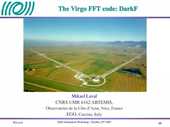
The Virgo FFT code: DarkF. Mikael Laval CNRS UMR 6162 ARTEMIS, Observatoire de la Côte d’Azur, Nice, France EGO, Cascina, Italy. Outlines. Introduction Using DarkF The three kinds of simulation The simulation parameters Mirror maps Ideal locking position

E N D
The Virgo FFT code: DarkF Mikael Laval CNRS UMR 6162 ARTEMIS, Observatoire de la Côte d’Azur, Nice, France EGO, Cascina, Italy
Outlines • Introduction • Using DarkF • The three kinds of simulation • The simulation parameters • Mirror maps • Ideal locking position • Results given by an automatic simulation • Examples of DarkF use • Conclusion • Phase camera • Input mode cleaner • Flat modes .vs. LG high order modes
Introduction • DarkF is an optical simulation code using a plane wave decomposition to propagate the wavefronts.It has been written by Jean-Yves Vinet and Mikael Laval (language Fortran90). • It uses the Fourier transform method to propagate the beam. • Beams and mirrors are sampled on a grid (x,y) and the DarkF resolution is depending of the grid size and of the point number (typically a size of 0.7m (larger than a mirror) with 128*128 points). • We can include the mirror surface maps and the thermal effect phase maps in the simulation after correction of the residual tilt and of the piston. • We can simulate simple systems such as Fabry Perot cavities (resonant or not), Michelson interferometers or complex systems as Virgo (for the carrier and for the sidebands).
Using DarkF (1/2) DarkF is complex but it has been coded to have a semi-automatic version. A user’s guide is in the final edition stage. DarkF is composed by a main program, 8 modules and 3 parameter files. The Virgo user will have to modify the parameter list and to choose the kinds of simulation. The “kind of simulation” One of the DarkF parameters is the “kind of simulation”. Three kinds are available but only the first two are automatic. • “Main”: With this parameter, DarkF will simulate the Virgo interferometer but only for the carrier. • “Main&SB”: This second kind will simulate the Virgo interferometer for the carrier and the sidebands.
Using DarkF (2/2) • “Free”: It is the expert mode! This mode will be used to obtain a specific results which is not in the result file of the automatic modes or when the user does not want to simulate the Virgo interferometer. But in this mode, the user has to code his simulation in the main program. Consequently this mode is for the users which have a good knowledge of DarkF and of its possibilities. Remark: For the first two kinds of simulation, it is not necessary to compile the code. But for the case “Free”, a new compilation will be essential. Consequently a Makefile has been created for several configurations: • Fortran compiler: g95 or pathf95 • FFT library: FFTW or ACML
The simulation parameters We have three parameter files for DarkF: • paramfiles.in: This is the parameter file which defines the name of the other parameter files and of the result file. • paramsimu.in: This is the parameter file of the simulation (size of the sampling window, number of points of the window, power of the initial beams, waist, kind of simulation, modulation frequency, interferometer lengths,…). • paramirrors.in: This file contains all the mirror parameters (transmission, losses, tilt, rotation,…) and the name of the mirror maps.
Mirror maps The mirrors maps can be tilted, rotated by 180° or translated. We can also modify the roughness amplitude to see its effects. For the curved mirrors, the mirror map corresponds to the roughness. Then we add this roughness to a paraboloid. Consequently it is easy to modify the curvature of these mirrors.
Ideal locking position in DarkF • DarkF does not use the same method as Virgo to lock the interferometer. To lock, DarkF uses only the carrier. The locking position is checked when we have the maximum of power in the long arms, in the recycling cavity and the minimum on the output. • Tuning of the long arms: We modify the propagator to have a null phase shift after a round trip. • Tuning of the dark fringe: West arm Beam Splitter eref1 North arm eref2 We calculate α and correct the propagator phase between the beam splitter and the west input mirror by α/2. edf2 edf1 • Tuning of the recycling cavity: Recycling Mirror e0tr We calculate α and correct the propagator phase between the beam splitter and the recycling mirror by α/2. eref
Results given by an automatic simulation • The configuration • The parameters • The results of the simulation (power of the different beams, the losses, the coupling defect, the coupling of the main beams with perfect TEM, the main beam baric center,…) • Result file: • Beam files: The main beam intensity is saved in different files called as the beams in the code. Consequently we can plot the beam shape with a Matlab code.
Examples of DarkF useThe Virgo Phase Camera (Cold interferometer) In the present phase camera (which is after the antireflective coating of the beam splitter), the contributions of both sidebands are summed. Consequently, we cannot distinguish them. It will be in an up-graded version of the phase camera. Carrier: LSB: USB: Phase camera signal: Virgo signal DarkF simulation Equivalent tilt = 1.6μrad Probably Virgo tilts the mirrors to compensate.
Examples of DarkF useThe Virgo Phase Camera (Warm interferometer) Warm interferometer: dn/dT=0.98 e-5 K-1 Absorption(NI) = 5ppm P(absorbed)=25mWAbsorption(WI) = 13.8ppm P(absorbed)=69mW Virgo signal DarkF simulation
Examples of DarkF useThe Virgo Phase Camera (Thermalization) As the effects of the thermal compensation system developed by Roma group will be measured only by the phase camera, DarkF should be useful to give many important information.
Input Mode Cleaner CharacterizationConfiguration C03004radius=3,64cmRc=179,601mT=5,7ppmLosses=66,2ppmRotation: 17° DarkF simulation: Diaphragms:radius=1,75cm L=143,573m TEM00 (width w0)Waist on input mirror d=8,65cmneglected 99061radius=1,96cmT=2457ppmLosses=15ppm 99059radius=1,96cmT=2427ppmLosses=37ppm Sampling step = 0,47mm
Input Mode Cleaner CharacterizationResults Nomenclature: IM = Input Mirror; OM = Output Mirror; EM = End Mirror (or curved mirror)L(round trip) = Losses during a round trip, mirror losses not includedC = CouplingSc = Clipping (or Screening)Diaphragm1 = between EM and IM; Diaphragm2 = between OM and EMe0 = injected beam (TEM00)eIMC = intracavity beam General results Clipping by mirror
Flat modes .vs. LG high order modes Why using flat modes or Laguerre Gauss high order modes as incoming beam? To have a better distribution of the power on the mirror surfaces. The surface deformations are averaged and the thermal noise contribution to the sensitivity is reduced. The heating of the mirrors will be more uniform and thermal lensing should be less important. Problems: What mirror size is necessary to not have clipping losses? What are the effects of a mismatching? What are the specifications needed for the alignment (tilt and centering of the mirrors)?
L=3km Etr Ecav E0 Eref M1 M2 Configuration (1/2) Cavity for LG modes (Finesse=25): E0=LG33 or LG55(matched with the cavity)Waist at the cavity center = 2,29cmWidth on the mirror=3,19cm T=11,8%Losses=0Rc=3100mradius r
L Etr E0 Ecav Eref M1 M2 Configuration (2/2) Cavity for flat modes (Finesse=25): T=11,8%Losses=0radius r M1 = perfect flat mirrorM2 = conjugate of twice a perfect flat mode argument in L=3km E0 = prefect flat mode = sum of tem00 of waist 3,188cm on a area of radius 11,3cm
Results To have less than 1ppm for the clipping losses or less than 10% decrease of the storage amplification:(p=precision)
Detuning of the cavityLG modes We detune the cavity (end mirror tilted by 0.2μrad ; finesse = 500):
Detuning of the cavityFlat modes (1/2) We detune the cavity (end mirror tilted by 0.2μrad ; finesse = 500): 1 9 10 2 3 5 4 6,7 8
Conclusion • DarkF is now developed enough to be used by the Virgo collaboration. The executable file and the user’s guide will be installed on a computer center. • DarkF is used for the Optical Characterization (Virgo phase camera, recycling length, sideband dissymmetry, modulation frequency, input mode cleaner,…) but also for the Advanced Virgo R&D: Study of the flat modes and of the LG high order modes. • The development of DarkF will continue: • new method of locking close to the Virgo one • For the R&D, we need to create some large mirror maps