Download
1 / 15
150 likes | 287 Vues
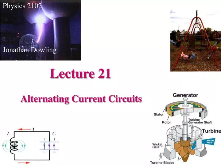
Physics 2102 Jonathan Dowling. Lecture 21. Alternating Current Circuits. Alternating Current:. To keep oscillations going we need to drive the circuit with an external emf that produces a current that goes back and forth. Notice that there are two frequencies

E N D
Physics 2102 Jonathan Dowling Lecture 21 Alternating Current Circuits
Alternating Current: To keep oscillations going we need to drive the circuit with an external emf that produces a current that goes back and forth. Notice that there are two frequencies involved: one at which the circuit would oscillate “naturally”. The other is the frequency at which we drive the oscillation. However, the “natural” oscillation usually dies off quickly (exponentially) with time. Therefore in the long run, circuits actually oscillate with the frequency at which they are driven. (All this is true for the gentleman trying to make the lady swing back and forth in the picture too).
Alternating Current: We have studied that a loop of wire, spinning in a constant magnetic field will have an induced emf that oscillates with time, That is, it is an AC generator. AC’s are very easy to generate, they are also easy to amplify and decrease in voltage. This in turn makes them easy to send in distribution grids like the ones that power our homes. Because the interplay of AC and oscillating circuits can be quite complex, we will start by steps, studying how currents and voltages respond in various simple circuits to AC’s.
AC Driven Circuits: 1) A Resistor: For time dependent periodic situations it is useful to represent magnitudes using “phasors”. These are vectors that rotate at a frequency wd , their magnitude is equal to the amplitude of the quantity in question and their projection on the vertical axis represents the instantaneous value of the quantity under study. Resistors behave in AC very much as in DC, current and voltage are proportional (as functions of time in the case of AC), that is, they are “in phase”.
AC Driven Circuits: 2) Capacitors: Capacitors “oppose a resistance” to AC (reactance) of frequency-dependent magnitude 1/wd C (this idea is true only for maximum amplitudes, the instantaneous story is more complex).
AC Driven Circuits: 3) Inductors: Inductors “oppose a resistance” to AC (reactance) of frequency-dependent magnitude wd L (this idea is true only for maximum amplitudes, the instantaneous story is more complex).
Emsin(dt) ~ IR IC C IL L Impedance ( or reactance): R All elements in parallel: VR, VC, VL • Once again: • VR is always in phase with IR; • VL leads IL by 900 • IC leads VC by 900 • “ELI the ICE man...”
Rms, peak and peak-to-peak: If E=Emsin(dt) Then the peak-to-peak emf is 2Em; The amplitude of the emf is Em (peak) The rms emf is Em/2 Erms = 7.07 V f = 5 Hz Example: ~ • Circuit shown is driven by a low frequency (5 Hz) voltage source with an rms amplitude of 7.07 V. Compute the current amplitudes in the resistor, capacitor and inductor (IR, IC and IL, respectively). 10mF 10mH 100W
Example 2 (solution) Erms = 7.07 V f = 5 Hz Em = 10 V w = 10p rad/s ~ • The three components are in parallel across the driving emf. • Amplitude of voltage across the three components is the same. • So, current amplitude for any given component is inversely proportional to X: Im = Em/X • R = 100W IR = (10V)/(100W) = 0.1 A • XC = 1/(wC) = 1/(10p.10-5)= 3184W IC = (10V)/(3184W)=3.14 mA • XL = wL = 10p.10-2 = 0.314 W IL= (10V)/(0.314 W) = 31.85 A 10mF 10mH 100W
Driven RLC Circuit Inductors: f = +p/2 (V leads I) Capacitors: f = –p/2 (I leadsV) Resistors: f = 0 Phase differences between voltage and current!
Resulting emf: Current in circuit: Emf in devices: Series circuit: current is the same in all devices. Driven RLC Circuit “Taking a walk” we see that the emfs in the various devices should add up to that of the AC generator. But the emfs are out of phase with each other. How to add them up? Use phasors.
Driven RLC Circuit Applying Pythagoras’ theorem to the picture: Which resembles “i=E/R” Also for the phase:
Summary E= Em sin(dt); I = Imsin(dt - ) (We have used XR=R, XC=1/wC, XL=wL )
In a given series RLC circuit: Em = 125 V Im = 3.2 A Current LEADS source emf by 0.982 rad. Determine Z and R. Z = Em/ Im = (125/3.2) W = 39.1 W How to find R? Look at phasors! Emcos f= VR = ImR R = Emcos f/Im= (125V)(0.555)/(3.2A) = 21.7 W VR=ImR VL f Em=ImZ VC Example
VR Em VL- VC Example • In a given series RLC circuit: • VL = 2VR = 2VC. • Determine f. Hence, f = 450 VL Em VR f VC