Download
1 / 56
560 likes | 568 Vues
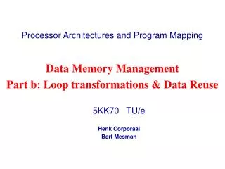
Processor Architectures and Program Mapping. Data Memory Management Part a: Overview. 5kk10 TU/e Henk Corporaal Jef van Meerbergen Bart Mesman. Data Memory Management Overview. Motivation Example application DMM steps Results Notes:

E N D
Processor Architectures and Program Mapping Data Memory Management Part a: Overview 5kk10 TU/e Henk Corporaal Jef van Meerbergen Bart Mesman
Data Memory Management Overview • Motivation • Example application • DMM steps • Results Notes: • We concentrate on Static Data structures like arrays • The Data Transfer and Storage Exploration (DTSE)methodology, on which these slides are based, has been developed at IMEC, Leuven Processor Architectures and Program Mapping H. Corporaal, J. van Meerbergen, and B. Mesman
Concurrent OO spec Remove OO overhead Dynamic memory mgmt Task concurrency mgmt Static memory mgmt Address optimization SW/HW co-design SW design flow HW design flow Design flow Processor Architectures and Program Mapping H. Corporaal, J. van Meerbergen, and B. Mesman
SDRAM SDRAM Serial I/O video-in B[j] = A[i*4+k]; B[j] = A[i*4+k]; B[j] = A[i*4+k]; PCI bridge video-out timers I2C I/O Data storage bottleneck audio-out I$ VLIW cpu audio-in Data transfer bottleneck D$ D$ The underlying idea for (i=0;i<n;i++) for (j=0; j<3; j++) for (k=1; k<7; k++) B[j] = A[i*4+k]; Processor Architectures and Program Mapping H. Corporaal, J. van Meerbergen, and B. Mesman
TriMedia (VLIW processor) 256M 1-port SDRAM Hardware accelerators 5 out of 27 processor FUs 128*32b 16-port RegFile 16K2-port SRAM 256M 1-port SDRAM TriMedia cache use CPU SW cache 8KB Cache bypass HW cache 8/16KB SW controlled HW controlled Platform example: TriMedia Processor Architectures and Program Mapping H. Corporaal, J. van Meerbergen, and B. Mesman
Platform architecture model Level-2 Level-3 Level-4 Level-1 SCSI bus bus bus Chip on-chip busses bus-if bridge SCSI Disk L2 Cache ICache CPUs DCache Main Memory Disk HW accel Local Memory Local Memory Disk Local Memory Processor Architectures and Program Mapping H. Corporaal, J. van Meerbergen, and B. Mesman
Power(memory) = 33 Power(arithmetic) Data transfer and storage power Processor Architectures and Program Mapping H. Corporaal, J. van Meerbergen, and B. Mesman
What about delay of memories? Global wiring delay becomes dominant over gate delay Processor Architectures and Program Mapping H. Corporaal, J. van Meerbergen, and B. Mesman
Data transfer and data storage specific rewrites in the application code Positioning in the Y-chart Architecture Instance Applications Applications Applications Mapping Performance Analysis Performance Numbers Processor Architectures and Program Mapping H. Corporaal, J. van Meerbergen, and B. Mesman
Mapping • Given • architecture e.g. TriMedia TM1000 • reference C code for applicatione.g. MPEG-4 Motion Estimation • Task • map application on architecture • But … wait a moment me@work> tmcc -o mpeg4_me mpeg4_me.cThank you for running TriMedia compiler.Your program uses 257321886 bytes,78 Watt, and 428798765291 clock cycles Processor Architectures and Program Mapping H. Corporaal, J. van Meerbergen, and B. Mesman
Let’s help the compiler ...DTSE: data transfer and storage exploration • Transforms C-code of the application • By focusing on multi-dimensional signals (arrays) • To better exploit platform capabilities • This overview covers the major steps to improve power, area, performance trade-off in the context of platform based design Processor Architectures and Program Mapping H. Corporaal, J. van Meerbergen, and B. Mesman
Application domain: Computer Tomography in medical imaging Algorithm: Cavity detection in CT-scans Detect dark regions in successive images Indicate cavity in brain Application example Bad news for owner of brain Processor Architectures and Program Mapping H. Corporaal, J. van Meerbergen, and B. Mesman
Application Max Value Reference (conceptual) C code for the algorithm • all functions: image_in[N x M]t-1 -> image_out[N x M]t • new value of pixel depends on its neighbors • neighbor pixels read from background memory • approximately 110 lines of C code (ignoring file I/O etc) • experiments with N x M = 640 x 400 pixels • straightforward implementation: 6 image buffers Gauss Blur x Gauss Blur y Compute Edges Reverse Detect Roots Processor Architectures and Program Mapping H. Corporaal, J. van Meerbergen, and B. Mesman
Avoid N-port Memories within real-time constraints local latch 1 & bank 1 Processor Data Paths L1 cache L2 cache Cache Bank Combine local latch N & bank N Introduce Locality Reduce redundant transfers Exploit memory hierarchy DMM (data mem. mgt.) principles Off-chip SDRAM Exploit limited life-time Processor Architectures and Program Mapping H. Corporaal, J. van Meerbergen, and B. Mesman
C-in DMM steps Preprocessing Dataflow transformations Loop transformations Data reuse Memory hierarchy layer assignment Cycle budget distribution Memory allocation and assignment Data layout Address optimization C-out Processor Architectures and Program Mapping H. Corporaal, J. van Meerbergen, and B. Mesman
The DM steps • Preprocessing • Rewrite code in 3 layers (parts) • Selective inlining, Single Assignment form, .... • Data flow transformations • Eliminate redundant transfers and storage • Loop and control flow transformations • Improve regularity of accesses and data locality • Data re-use and memory hierarchy layer assignment • Determine when to move which data between memories to meet the cycle budget of the application with low cost • Determine in which layer to put the arrays (and copies) Processor Architectures and Program Mapping H. Corporaal, J. van Meerbergen, and B. Mesman
The DM steps Per memory layer: • Cycle budget distribution • determine memory access constraints for given cycle budget • Memory allocation and assignment • which memories to use, and where to put the arrays • Data layout • determine how to combine and put arrays into memories • Address optimization on the final C-code Processor Architectures and Program Mapping H. Corporaal, J. van Meerbergen, and B. Mesman
for (i=0;i<N; i++) for (j=0; j<M; j++) if (i == 0) B[i][j] = 1; else B[i][j] = func1(A[i][j], A[i-1][j]); Preprocessing: Dividing an application in the 3 layers Module1a LAYER1 Module2 Module3 Module1b - testbench call - dynamic event behaviour Synchronisation - mode selection LAYER2 int func1(int a, int b) LAYER3 { return a*b; } Processor Architectures and Program Mapping H. Corporaal, J. van Meerbergen, and B. Mesman
Layered code structure main(){ /* Layer 1 code */ read_image(IN_NAME, image_in); cav_detect(); write_image(image_out); } void cav_detect() { /* Layer 2 code */ for (x=GB; x<=N-1-GB; ++x) { for (y=GB; y<=M-1-GB; ++y) { gauss_x_tmp = 0; for (k=-GB; k<=GB; ++k) { gauss_x_tmp += in_image[x+k][y] * Gauss[abs(k)]; } gauss_x_image[x][y] = foo(gauss_x_tmp); } } } Processor Architectures and Program Mapping H. Corporaal, J. van Meerbergen, and B. Mesman
N M N-2 M-2 Data-flow trafo - cavity detection for (x=0; x<N; ++x) for (y=0; y<M; ++y) gauss_x_image[x][y]=0; for (x=1; x<=N-2; ++x) { for (y=1; y<=M-2; ++y) { gauss_x_tmp = 0; for (k=-1; k<=1; ++k) { gauss_x_tmp += image_in[x+k][y]*Gauss[abs(k)]; } gauss_x_image[x][y] = foo(gauss_x_tmp); } } #accesses: N * M + (N-2) * (M-2) Processor Architectures and Program Mapping H. Corporaal, J. van Meerbergen, and B. Mesman
N M M-2 N-2 Data-flow trafo - cavity detection for (x=0; x<N; ++x) for (y=0; y<M; ++y) if ((x>=1 && x<=N-2) && (y>=1 && y<=M-2)) { gauss_x_tmp = 0; for (k=-1; k<=1; ++k) { gauss_x_tmp += image_in[x+k][y]*Gauss[abs(k)]; } gauss_x_image[x][y] = foo(gauss_x_tmp); } else { gauss_x_image[x][y] = 0; } } } #accesses: N * M gain is almost 50 % Processor Architectures and Program Mapping H. Corporaal, J. van Meerbergen, and B. Mesman
Data-flow transformation • In total 5 types of data-flow transformations: • advanced signal substitution and (copy) propagation • algebraic transformations (associativity etc.) • shifting “delay lines” • re-computation • transformations to eliminate bottlenecksfor subsequent loop transformations Processor Architectures and Program Mapping H. Corporaal, J. van Meerbergen, and B. Mesman
Data-flow transformation - result Processor Architectures and Program Mapping H. Corporaal, J. van Meerbergen, and B. Mesman
for (j=1; j<=M; j++) for (i=1; i<=N; i++) A[i]= foo(A[i]); for (i=1; i<=N; i++) out[i] = A[i]; for (i=1; i<=N; i++) { for (j=1; j<=M; j++) { A[i] = foo(A[i]); } out[i] = A[i]; } storage size 1 storage size N Loop transformations • Loop transformations • improve regularity of accesses • improve temporal locality: production consumption • Expected influence • reduce temporary storage and (anticipated) background storage Processor Architectures and Program Mapping H. Corporaal, J. van Meerbergen, and B. Mesman
Global loop transformation steps applied to cavity detection • Make all loop dimensions equal • Regularize loop traversal:Y and X loop interchange • follow order of input stream • Y loop folding and global mergingX loop folding and global merging • full, global scope regularity • nearly complete locality for main signals Processor Architectures and Program Mapping H. Corporaal, J. van Meerbergen, and B. Mesman
scandevice Data enters Cavity Detectorrow-wise serial scan Buffer =image_in GaussBlur loop Cavity Detector Processor Architectures and Program Mapping H. Corporaal, J. van Meerbergen, and B. Mesman
N x M Gauss Blur x X-Y Loop Interchange Loop trafo - cavity detection N x M Scanner X Y From double bufferto single buffer Processor Architectures and Program Mapping H. Corporaal, J. van Meerbergen, and B. Mesman
Loop interchange (Y X) • Not always possible; check dependences • For all loops, to maintain regularity for (x=0;x<N;x++) for (y=0;y<M;y++) /* filtering code */ for (y=0;y<M;y++) for (x=0;x<N;x++) /* filtering code */ Processor Architectures and Program Mapping H. Corporaal, J. van Meerbergen, and B. Mesman
Loop trafo - cavity detection N x (2GB+1) N x 3 Gauss Blur x Gauss Blur y Compute Edges Repeated fold and loop merge 3(offset arrays) 2GB+1 From N x M toN x (3) buffer size From N x M toN x (2GB+1) buffer size Processor Architectures and Program Mapping H. Corporaal, J. van Meerbergen, and B. Mesman
Improve regularity and locality Loop Merging !! Impossible due to dependencies! for (y=0;y<M;y++) for (x=0;x<N;x++) /* 1st filtering code */ for (y=0;y<M;y++) for (x=0;x<N;x++) /* 2nd filtering code */ for (y=0;y<M;y++) for (x=0;x<N;x++) /* 1st filtering code */ for (x=0;x<N;x++) /* 2nd filtering code */ Processor Architectures and Program Mapping H. Corporaal, J. van Meerbergen, and B. Mesman
Data dependencies between1st and 2nd loop for (y=0;y<M;y++) for (x=0;x<N;x++) … gauss_x_image[x][y] = … for (y=0;y<M;y++) for (x=0;x<N;x++) … for (k=-GB; k<=GB; k++) … = … gauss_x_image[x][y+k] … Processor Architectures and Program Mapping H. Corporaal, J. van Meerbergen, and B. Mesman
Enable merging withLoop Folding (bumping) for (y=0;y<M;y++) for (x=0;x<N;x++) … gauss_x_image[x][y] = … for (y=0+GB;y<M+GB;y++) for (x=0;x<N;x++) … y-GB … for (k=-GB; k<=GB; k++) … gauss_x_image[x][y+k-GB] … Processor Architectures and Program Mapping H. Corporaal, J. van Meerbergen, and B. Mesman
Y-loop merging on 1st and 2nd loop nest for (y=0;y<M+GB;y++) if (y<M) for (x=0;x<N;x++) … gauss_x_image[x][y] = … if (y>=GB) for (x=0;x<N;x++) if (x>=GB && x<=N-1-GB && (y-GB)>=GB && (y-GB)<=M-1-GB) … for (k=-GB; k<=GB; k++) … gauss_x_image[x][y-GB+k] … else Processor Architectures and Program Mapping H. Corporaal, J. van Meerbergen, and B. Mesman
Simplify conditions in merged loop for (y=0;y<M+GB;y++) for (x=0;x<N;x++) if (y<M) … gauss_x_image[x][y] = … for (x=0;x<N;x++) if (y>=GB && x>=GB && x<=N-1-GB && (y-GB)>=GB && (y-GB)<=M-1-GB) … for (k=-GB; k<=GB; k++) … gauss_x_image[x][y-GB+k] … else if (y>=GB) Processor Architectures and Program Mapping H. Corporaal, J. van Meerbergen, and B. Mesman
Global loop merging/folding steps 1 x y Loop interchange (done) 2 Global y-loop folding/merging: 1st and 2nd nest (done) 3 Global y-loop folding/merging: 1st/2nd and 3rd nest 4 Global y-loop folding/merging: 1st/2nd/3rd and 4th nest 5 Global x-loop folding/merging: 1st and 2nd nest 6 Global x-loop folding/merging: 1st/2nd and 3rd nest 7 Global x-loop folding/merging: 1st/2nd/3rd and 4th nest Processor Architectures and Program Mapping H. Corporaal, J. van Meerbergen, and B. Mesman
End result of global loop trafo for (y=0; y<M+GB+2; ++y) { for (x=0; x<N+2; ++x) { … if (x>=GB && x<=N-1-GB && (y-GB)>=GB && (y-GB)<=M-1-GB) { gauss_xy_compute[x][y-GB][0] = 0; for (k=-GB; k<=GB; ++k) gauss_xy_compute[x][y-GB][GB+k+1] = gauss_xy_compute[x][y-GB][GB+k] + gauss_x_image[x][y-GB+k] * Gauss[abs(k)]; gauss_xy_image[x][y-GB] = gauss_xy_compute[x][y-GB][(2*GB)+1]/tot; } else if (x<N && (y-GB)>=0 && (y-GB)<M) gauss_xy_image[x][y-GB] = 0; … Processor Architectures and Program Mapping H. Corporaal, J. van Meerbergen, and B. Mesman
Loop transformations - result Processor Architectures and Program Mapping H. Corporaal, J. van Meerbergen, and B. Mesman
M’’ M’ M Main memory P = 0.01 P = 0.1 P = 1 Data re-use & memory hierarchy • Introduce memory hierarchy • reduce number of reads from main memory • heavily accessed arrays stored in smaller memories Processor Data Paths Reg File #A = 100 100 10 1 P (original) = # access x power/access = 100 P (after) = 100 x 0.01 + 10 x 0.1 + 1 x 1 = 3 Processor Architectures and Program Mapping H. Corporaal, J. van Meerbergen, and B. Mesman
int[2][6] A;for (h=0; h<N; h++) for (i=0; i<2; i++) for (j=0; j<3; j++) for (k=1; k<7; k++) B[j] = A[i][k]; array index (6 * i + k) iterations Data re-use • Data flow transformations to introduce extracopies of heavily accessed signals • Step 1: figure out data re-use possibilities • Step 2: calculate possible gain • Step 3: decide on data assignment to memory hierarchy Processor Architectures and Program Mapping H. Corporaal, J. van Meerbergen, and B. Mesman
array index 6*2 6*1 N*2*3*6 iterations frame1 frame2 frame3 CPU Data re-use • Data flow transformations to introduce extracopies of heavily accessed signals • Step 1: figure out data re-use possibilities • Step 2: calculate possible gain • Step 3: decide on data assignment to memory hierarchy 1*2*1*6 N*2*1*6 Processor Architectures and Program Mapping H. Corporaal, J. van Meerbergen, and B. Mesman
Data re-use tree image_in gauss_xy/comp_edge gauss_x image_out N*M M*3 M*3 M*3 N*M N*M N*M*3 N*M*3 N*M 0 1*1 N*1 3*3 1*3 N*M N*M*8 N*M*8 N*M*3 3*1 N*M*3 CPU CPU CPU CPU CPU Processor Architectures and Program Mapping H. Corporaal, J. van Meerbergen, and B. Mesman
L3 L2 L1 Memory hierarchy assignment image_in image_out gauss_xy comp_edge gauss_x N*M N*M 1MB SDRAM 0 N*M M*3 M*3 M*3 16KB Cache N*M*3 N*M N*M N*M*3 N*M*3 128 B RegFile 1*1 1*1 3*1 3*3 3*3 N*M*3 N*M*8 N*M*8 N*M*8 N*M*8 Processor Architectures and Program Mapping H. Corporaal, J. van Meerbergen, and B. Mesman
Data-reuse - cavity detection code Code before reuse transformation for (y=0; y<M+3; ++y) { for (x=0; x<N+2; ++x) { if (x>=1 && x<=N-2 && y>=1 && y<=M-2) { gauss_x_tmp = 0; for (k=-1; k<=1; ++k) gauss_x_tmp += image_in[x+k][y]*Gauss[abs(k)]; gauss_x_image[x][y]= foo(gauss_x_compute); } else { if (x<N && y<M) gauss_x_lines[x][y] = 0; } /* Other merged code omitted … */ } } Processor Architectures and Program Mapping H. Corporaal, J. van Meerbergen, and B. Mesman
Data-reuse - cavity detection code Code after reuse transformation: for (y=0; y<M+3; ++y) { for (x=0; x<N+2; ++x) { /* first in_pixels initialized */ if (x==0 && y>=1 && y<=M-2) for (k=0; k<1; ++k) in_pixels[(x+k)%3] = image_in[x+k][y]; /* copy rest of in_pixels in row */ if (x>=0 && x<=N-2 && y>=1 && y<=M-2) in_pixels[(x+1)%3] = image_in[x+1][y]; if (x>=1 && x<=N-1-1 && y>=1 && y<=M-2) { gauss_x_tmp=0; for (k=-1; k<=1; ++k) gauss_x_tmp += in_pixels[(x+k)%3]*Gauss[Abs(k)]; gauss_x_lines[x][y%3]= foo(gauss_x_tmp); } else if (x<N && y<M) gauss_x_lines[x][y%3] = 0; Processor Architectures and Program Mapping H. Corporaal, J. van Meerbergen, and B. Mesman
Data reuse & memory hierarchy Processor Architectures and Program Mapping H. Corporaal, J. van Meerbergen, and B. Mesman
Data layout optimization • At this point multi-dimensional arraysare to be assigned to physical memories • Data layout optimization determines exactly where in each memory an array should be placed, to • reduce memory size by “in-placing” arrays that do not overlap in time (disjoint lifetimes) • to avoid cache misses due to conflicts • exploit spatial locality of the data in memory to improve performance of e.g. page-mode memory access sequences Processor Architectures and Program Mapping H. Corporaal, J. van Meerbergen, and B. Mesman
A A A A D D B B D D C C C C B B E E E E In-place mapping Inter in-place Both intra+inter addresses Intra in-place time Processor Architectures and Program Mapping H. Corporaal, J. van Meerbergen, and B. Mesman
0x0 b8 mem1[10400]; for (i,j,k,l; …) mem1[10000+i+20*j] = f(mem1[10000+j+20*i], b6(mem1[i+k+100*(j+l)]); A 0x2710 B 0x28a0 In-place mapping • Implements all the “anticipated” memory size savings obtained in previous steps • Modifies code to introduce one array per “real” memory • Changes indices to addresses in mem. arrays b8 A[100][100]; b6 B[20][20]; for (i,j,k,l; …) B[i][j] = f(B[j][i], A[i+k][j+l]); Processor Architectures and Program Mapping H. Corporaal, J. van Meerbergen, and B. Mesman
address Image time In-place mapping • Input image is partly consumed by the time first results for output image are ready index Image_in time index Image_out time Processor Architectures and Program Mapping H. Corporaal, J. van Meerbergen, and B. Mesman
In-place - cavity detection code for (y=0; y<=M+3; ++y) { for (x=0; x<N+5; ++x) { image_out[x-5][y-3] = …; /* code removed */ … = image_in[x+1][y]; } } for (y=0; y<=M+3; ++y) { for (x=0; x<N+5; ++x) { image[x-5][y-3] = …; /* code removed */ … = image [x+1][y]; } } Processor Architectures and Program Mapping H. Corporaal, J. van Meerbergen, and B. Mesman