Download
1 / 16
160 likes | 353 Vues
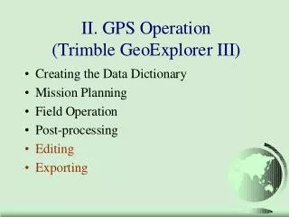
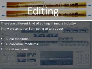
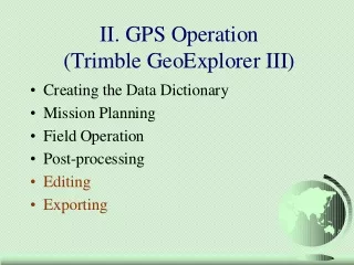
EDITING. How to make your own!. Green is County boundary. Yellow is soils layer (NRCS). This is called the “Coincident Line” problem. Orthophoto background. Shape files FC Coverages ArcINFO format PC ArcInfo format Rasters of various kinds TINs (Triangulated Irregular Networks)

E N D
EDITING How to make your own!
Green is County boundary Yellow is soils layer (NRCS) This is called the “Coincident Line” problem Orthophoto background esf Laboratory for Applied GIS
Shape files FC Coverages ArcINFO format PC ArcInfo format Rasters of various kinds TINs (Triangulated Irregular Networks) Networks Can edit Can edit Cannot edit in ArcMap Can’t even open in ArcMap* nope Yup Yup File types * Open in ArcView 3.3 & save as a shapefile esf Laboratory for Applied GIS
Editing Steps • Load only the data needed for editing into ArcMap • Click on the “Selection” tab at the bottom of the TOC (demo) • Make sure only the layer to be edited is selected • This gets around the Booby Trap of having the wrong layer in the Target window! esf Laboratory for Applied GIS
Setup • Load Edit toolbar • Set Task • Set Target esf Laboratory for Applied GIS
Set Snapping • Snapping environment • Select “snapping” from Edit dropdown • Priority of snappingis the order of thelayers (drag ‘em’). • In this case the mills will be snapped to the road’s edges. • Set snapping Tolerance (how close for jump) • Edit/options D esf Laboratory for Applied GIS
Snapping tricks • Press “T” will show you what the current snapping tolerance is… • If you need to change the snapping tolerance often then load the interactive snap tolerance toll to any tool bar • Rt clk blank spot on menu bar, scroll down to the bottome of the list that appears and click cutomize. Click the Command tab and then Edit and scroll down to the tool • Drag it to any tool bar (Edit, perhaps) • Clicking on the tool allows you to draw a circle that is the snapping tolerance you need. esf Laboratory for Applied GIS
Setting Snapping Stuff Pixels or map units No, No, No Distance between vertices Number of vertices to be deleted when you screw up – and you will when using stream mode! Tip says what you are snapped to esf Laboratory for Applied GIS
Sketch Construction Tools: Sketch tool Use the Sketch tool to create point features and digitize the vertices of line or polygon features. After you finish the sketch, ArcMap adds the final segment, and the sketch turns into a feature. esf Laboratory for Applied GIS
Sketch Construction Tools: ArcTool The Arc tool helps you create a segment that is a parametric (true) curve. Instead of being made of numerous vertices, a parametric curve has only two vertices as endpoints. esf Laboratory for Applied GIS
Sketch Construction Tools - midpoint The Midpoint tool lets you define the location of the next vertex by clicking two points; the new vertex is placed at the midpoint of the line between these points. esf Laboratory for Applied GIS
Midpoint tool? D esf Laboratory for Applied GIS
Sketch Construction Tools The Trace tool helps you create segments that Follow along parallel to an existing segment. esf Laboratory for Applied GIS
Traces along an existing line features (instead of typing the angle and length of each segment.) select the parcel features before you can start tracing the road casing feature. The Trace tool only follows selected features. Trace tool D esf Laboratory for Applied GIS
Split Poly Tool • Use the “Cut Polygon Features” task • Why • Makes a perfect match between polys when Split – every time and… • Select poly to split with the Edit Tool • Use pencil tool to draw a line through the poly where you want it split • Rt click anywhere to finish the job esf Laboratory for Applied GIS
IMPORTANT STUFF • 3Ts • TARGET • TASK • TOOL • 3Ss • Snapping What • Snapping distance • Selection esf Laboratory for Applied GIS