Download
1 / 47
480 likes | 724 Vues
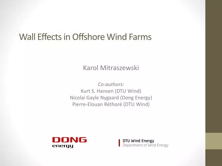
Wall Effects in Offshore Wind Farms. Karol Mitraszewski Co- authors : Kurt S. Hansen (DTU Wind) Nicolai Gayle Nygaard (Dong Energy) Pierre-Elouan Réthoré (DTU Wind). 1. Motivation. A generic offshore wind farm. Wind coming from the open sea. COMMON MODEL PREDICTIONS:.

E N D
Wall Effects in Offshore Wind Farms Karol Mitraszewski Co-authors: Kurt S. Hansen (DTU Wind) Nicolai Gayle Nygaard (Dong Energy) Pierre-Elouan Réthoré (DTU Wind)
1. Motivation A generic offshore wind farm Wind coming from the open sea COMMON MODEL PREDICTIONS: OBSERVATIONS FROM A NUMBER OF OFFSHORE WIND FARMS: Power outputs of turbines located in the outer edges of the farm differ significantly, order of magnitude of these differences: 10% ! What are the causes of these effects? How often do they occur? Are they at all significant? Are theyimportant in terms of AEP? Let’s introduce the name: WALL EFFECTS
2. Approach Quantify the wall effects by analyzing power outputs of turbines located in outer edges of the Horns Rev 1 farm (10 min. SCADA data) depending on wind direction, wind speed, turbulence intensity and stability for wake-free flow cases. „Ambient” wind signal derived from two „leader” turbines located in the analyzed edge, towards the center of the cluster (looking downwind): • Wind speed derived based on power & pitch curves • Wind direction based on nacelle position • Turbulence intensity based on std. deviation of electric power measurement • Leading turbine choice flow case dependent
3. Presentation of results Wind direction impact, western (onshore) winds Direction of arrows = „ambient” wind direction Color of arrow heads = power output relative to the mean of the highlighted row Basic statistics of the data base query Minimum power output in the outer edge = green cross Maximum power output in the outer edge = red cross COAST app.13 km away OPEN SEA
3. Presentation of results Wind direction impact, western (onshore) winds
3. Presentation of results Wind direction impact, western (onshore) winds
3. Presentation of results Wind direction impact, western (onshore) winds
3. Presentation of results Wind direction impact, western (onshore) winds
3. Presentation of results Wind direction impact, western (onshore) winds
3. Presentation of results Wind direction impact, western (onshore) winds
3. Presentation of results Wind direction impact, western (onshore) winds
3. Presentation of results Wind direction impact, western (onshore) winds
3. Presentation of results Wind direction impact, western (onshore) winds
3. Presentation of results Wind direction impact, western (onshore) winds
3. Presentation of results Wind direction impact, western (onshore) winds
3. Presentation of results Wind direction impact, western (onshore) winds
3. Presentation of results Wind direction impact, western (onshore) winds
3. Presentation of results Wind direction impact, western (onshore) winds
3. Presentation of results Wind direction impact, western (onshore) winds
3. Presentation of results Wind direction impact, western (onshore) winds
3. Presentation of results Wind direction impact, western (onshore) winds
3. Presentation of results Wind direction impact, eastern (offshore) winds COAST app.13 km away OPEN SEA
3. Presentation of results Wind direction impact, eastern (offshore) winds
3. Presentation of results Wind direction impact, eastern (offshore) winds
3. Presentation of results Wind direction impact, eastern (offshore) winds
3. Presentation of results Wind direction impact, eastern (offshore) winds
3. Presentation of results Wind direction impact, eastern (offshore) winds
3. Presentation of results Wind direction impact, eastern (offshore) winds
3. Presentation of results Wind direction impact, eastern (offshore) winds
3. Presentation of results Wind direction impact, eastern (offshore) winds
3. Presentation of results Wind direction impact, eastern (offshore) winds
3. Presentation of results Wind direction impact, eastern (offshore) winds
3. Presentation of results Wind direction impact, eastern (offshore) winds
3. Presentation of results Wind direction impact, eastern (offshore) winds
3. Presentation of results Wind direction impact, eastern (offshore) winds
3. Presentation of results Wind direction impact, eastern (offshore) winds
3. Presentation of results Wind direction impact, eastern (offshore) winds
3. Presentation of results Wind direction impact, eastern (offshore) winds
3. Presentation of results Wind direction impact, eastern (offshore) winds
3. Presentation of results Wind direction impact, observed trends For western winds the speed-up zone occurs consequently on the left sideof the cluster (looking downwind) despite changing orientation of the wind with respect to the layout and coast. For eastern winds the speed-up zone occurs consequently „further out offshore” despite changing orientation of the wind with respect to the layout and shore. The observed wall effects are both qualitatively as well as quantitatively different for eastern and western winds, hence: The driving mechanism of wall effects is different for eastern and western winds Shore vicinity has an impact on wall effects
3. Presentation of results Wind speed, turbulence and stability impacts • Wall effects decrease with wind speed • Wall effects decrease with turbulence intensity • Wall effects are most profound under stable atmospheric conditions • For more detailed information please consult the full text of the paper
4. Results interpretation Physical wall effect driving mechanisms, two regimes Two regimes „Coriolis regime” under western winds. „Coastal regime” under eastern winds The division is not a "clear cut"
4. Results interpretation Physical wall effect driving mechanisms, Coriolis regime Why is the speed-up region occuring always on the left of the cluster (looking downwind) ? What’s the source of asymmetry? Inspiration: Coriolis force driven streamline convergence/divergence is a documented phenomenon in coastal meteorology The streamline convergence mechanism is belived to be causing wall effects under western winds Streamline convergence/divergence causes acceleration/decceleration of the flow Although this is a hypothesis, observations supporting it can be found in wind farm related literature and coastal meteorology papers (see the full text of the paper)
4. Results interpretation Physical wall effect driving mechanisms, Coastal regime Gradual increase in wind speed at hub height with distance to shore under offshore winds is induced by the roughness change at the coast and the corresponding vertical profile change. This mechanism is causing the speed-up zone to appear „further-out offshore” under eastern winds at HR1
5. Results interpretation The impact of wall effects on AEP Hence the work done by Coriolis forces on a control volume of air is 0. Coastal effects are a site inherent feature Coriolis force is by definition always perpendicular to air particle velocity Coriolis effects are believed not to have an impact on AEP Only the wind direction is altered locally resulting in streamline convergence Wall effects are probably an „AEP neutral” phenomenon, although this hypothesis requires further scientific validation However, the Coriolis induced wake turning is not included in the present wake models
6. Summary of findings • Wall effects are a frequently occuring phenomenon • They are caused by Coriolis forces and coastal effects • They decrease with wind speed and turbulence intensity • The Coriolis induced wall effects at HR1 usually do not induce power output variations greater than 10% • The Coastal induced wall effects are more significant (up to 17%) (although this is very site specific) • Wall effects are probably AEP neutral • Further research: confirmation of the above presented hypotheses with the use of a meso-scale flow modeling tool. This task is being carried out in collaboration with: