Download
1 / 14
150 likes | 183 Vues
Metal Organic Chemical Vapour Deposition. 1. Abu Syed Md. Jannatul Islam Lecturer, Dept. of EEE, KUET, BD. Department of Electrical and Electronic Engineering Khulna University of Engineering & Technology Khulna-9203. MOCVD/OMVPE/OMCVD/MOVPE. 2.

E N D
Metal Organic Chemical Vapour Deposition 1 • Abu Syed Md. JannatulIslam • Lecturer, Dept. of EEE, KUET, BD • Department of Electrical and Electronic Engineering • Khulna University of Engineering & Technology • Khulna-9203
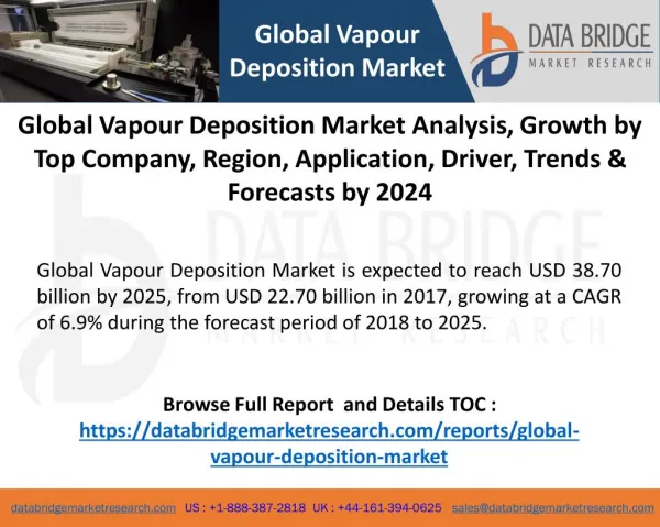
MOCVD/OMVPE/OMCVD/MOVPE 2 • MOCVD stands for Metal-Organic Chemical Vapour Deposition. • MOCVD is a technique that used to grow/deposit thin solid films, usually semiconductors, on solid substrates (wafers) using organo metallic compounds as sources. • The films grown by MOCVD are mainly used for the fabrication of electronic and optoelectronic devices. • The electronic and optoelectronic devices produced by MOCVD are used in cell phones , optical communication, optical storage (CD, DVD), traffic lights, bill boards (LEDs), lighting and solar cells. • Using MOCVD we can build up many layers, each of a precisely controlled thickness, to create a material which has specific optical and electrical properties.
Why MOCVD? 3 • Epitaxial films can be grown from solid, liquid, or gas phases. It is easier to control the growth rate in gas phase Epitaxy by controlling the flow of gases. • High grown layers quality, Highest flexibility • Faster growth rate than MBE, can be a few microns per hour; • Multi-wafer capability easily achievable. Different materials can be grown in the same system. • Doping uniformity/reproducibility, Economically advantageous. • High throughput and no ultra high vacuum needed (compared to MBE), • Precision in deposition thickness and possible sharp interfaces growth –thus, it is very suitable for hetero-structures, e.g., multi quantum wells (MQW) • Higher temperature growth; growth process is thermodynamically favorable
MOCVD Disadvantages 4 • Many materials that we wish to deposit have very low vapour pressures and thus are difficult to transport via gases • Not abruptable process as MBE due to gas flow issues • Human Hazard, that is, Toxic and corrosive gases are to be handled • High temperatures • Complex processes • Carbon contamination and unintentional Hydrogen incorporation are sometimes a problem
Schematic of MOCVD 5 • Main parts: • Source Supply System • Reactor • Exhaust System Fig. Simplified flow diagram of a MOCVD system
Schematic of MOCVD 6 Fig. Geometry of the Horizontal Reactor
MOCVD System 8 • Source Supply System: The different sources which are used are shown in Fig. • TMI (Trimethylindium) and TEG (Triethylgalium) are used as source material for In and Ga respectively. • NH3 is used as a source material for nitrogen. • N2 is used as a carrier gas to bring TMI and TEG into the reactor. • H2 gas is used for the thermal treatment of the substrate. • Reactive gases are fed in to the reactor through the mass flow controllers (MFC)
Main parts of MOCVD System 9 • Reaction Chamber/ Reactor: • Epitaxial vapor growth is made inside the reactor at different conditions (temperature, pressure, gas flow). • The substrates are placed on the susceptor. • Reactive gases are then fed into the reactor and these gases react on the substrate and form a grown film. • The heating method of this reactor is RF induction heating.
MOCVD System 10 • The deposition reaction, which takes place inside the reactor, for the grown of the nitride film is known as pyrolysis. • The formation of solid InN and GaN film on the substrate are happened by the following chemical reactions in vapor phase with the organometallic reactant species. For this reason it is called organo-metal vapor phase epitaxy. • (CH3)3 In + NH3 3CH4(v)+ InN(s) • Trimethal indium gas) (Amonnia gas) (Methane gas) (on the substrate) • (C2H5)3 Ga + NH3 3C2H6(v)+ GaN(s) • Triethylgalium gas) (Amonnia gas) (Ethane gas) (on the substrate) • (CH3)3 Ga + AsH3 3CH4 + GaAs • Trimethylgallium gas) (Arsene gas) (Methane gas) (on the substrate) • (CH3)3 In + PH3 3CH4 + InP • Trimethylgallium gas) (Phosphene gas) (Methane gas) (on the substrate)
MOCVD System 11 Exhaust System: The exhaust system consists of rotary and diffusion pump. When reactions are take place, the exhaust gases are then released to air through rotary pump and exhaust fan. Transport and Growth Mechanisms
MOCVD System 12 Deposition process takes place on the substrates (wafers)
Material Source should be 13 • Sufficiently volatile • High enough partial pressure to get good growth rates • Stable at room temperature • Produce desired element on substrate with easily removable by-products • Growth of III-V semiconductors: • Group III: generally metalorganic molecules (trimethyl- or triethyl- species) • Group V: generally toxic hydrides (AsH3; PH3 flammable as well); alternative: alkyls (TBAs, TBP).
Applications 14 Laser diode: Transistors LED Solar Cells