Download
1 / 21
210 likes | 346 Vues
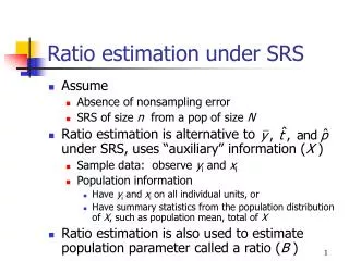
Maximizing the information/data ratio at run-time. G. Llort, J. González, H. Servat, J. Giménez, J. Labarta gllort@bsc.es. Tools scalability. >10k processes + long runs = large traces Blind tracing is not an option Profilers also start presenting issues Can you even store the data?

E N D
Maximizing the information/data ratio at run-time G. Llort, J. González, H. Servat, J. Giménez, J. Labarta gllort@bsc.es
Tools scalability >10k processes + long runs = large traces Blind tracing is not an option Profilers also start presenting issues Can you even store the data? How patient are you?
Workwithlarge traces Past methodology: Filters driven by the expert Get the whole trace Summarize for a global view Focus on a representative region Goal: Transfer the expertise to the run-time
Objectives • Traces of “100 Mb” • Best describe theapplicationbehavior • Trade-off: Maximizeinformation / data ratio • Thechallenge? • Intelligentselection of theinformation • How? • On-line analysisframework • Decide at run-time whatismostrelevant
Data acquisition Extrae (BSC) PMPI wrappers Data transmission MRNet (U. of Wisconsin) Scalable master / worker Tree topology Data analysis Clustering (BSC) Find structure of computing regions Applicationtasks Extrae attaches T0 T1 Tn Reduction Network MRNet Front-end ClusteringAnalysis … … …
Modules interaction Back-endthreads • Local trace buffers • BE threads blocked • FE periodically collects data • Automatic / fixed interval • Reduction on tree • Global analysis • Propagate results • Locally emit trace events T0 T1 Tn … Aggregate data Broadcast results MRNet Front-end ClusteringAnalysis
Clusteringanalysis • Density-based clustering algorithm • J. Gonzalez, J. Gimenez, J. Labarta – IPDPS'09 “Automatic detection of parallel applications computation phases” • Characterize structure of computing regions • Using hardware counters data • Instructions + IPC • Complexity & Performance • Any other metric • i.e. L1, L2 cache misses
Clusteringresults (WRF) ScatterPlot of ClusteringMetrics ClustersDistributionOver Time Clusters Performance CodeLinking
Tracking evolution Trigger clustering analysis periodically Sequence of structure snapshots Compare subsequent clusterings See changes in the application behavior Find a representative region Most applications are highly iterative
Selectrepresentative • Compare 2 clusterings, cluster per cluster • Inscribe clusters into a rectangle • Match those that overlap with a 5% variance • Sum of the matched clusters cover the 85% of total computing time • Stability = N equivalent clusterings “in-a-row” • Keep on looking for differences • Gradually lower requisites if can not be met • Best possible region based on “seen” results OK KO
Evolution of MILC 60 Mb, 6 iterations 1 2 3 4 5 6
Clustering vs. Classification Clustering time grows with the number of points 5k pts 10 sec, 50k pts 10 min Sample a subset of data to cluster (SDBScan) Space: Select a few processes. Full time sequence. Time: Random sampling. Wide covering. Classify remaining data Nearest neighbor algorithm Reusing clustering structures
Clustering vs. Classification Allprocesses 25% random records 32 representatives 15% random records 16 representatives 10% random records 8 representatives + 15% random 75% less data 6s downfrom 2m Goodquality Fastanalysis
Important trace size reductions Results before the application finishes Final trace is representative Experiments
Quality of the trace segment Compared vs. Profiles for the whole run TAU Performance System (U. of Oregon) Same overall structure Same relevant functions, Avg. HWC’s & Time % Most measurement differences under 1%
Example: GROMACS evolution ∑ % time matched clusters
Example: GROMACS structure • Studyload balancing Instructionsimbalance IPC imbalance
Increasingscale Initial development All data centralized Sampling, clustering & classification at front-end Bad scaling at large processor counts Workshop challenge: >10k tasks Sampling at leaves Only put together the clustering set Broadcast clustering results, classify at leaves
Conclusion On-line automatic analysis framework Identify structure and see how evolves Determine a representative region Detailed small trace + Periodic reports Reductions in the time dimension Scalable infrastructure supports other analyses Current work Spectral analysis (M. Casas): Better delineate the traced region Parallel clustering in the tree Finer stability heuristic
Thank you for your attention! On-line detection of large-scale parallel application’s structure, IPDPS 2010
Download • Open source (LGPL) • http://www.bsc.es/paraver • Paraver • Extrae (formerly MPItrace)