Download
1 / 42
420 likes | 522 Vues
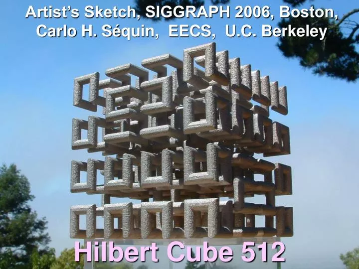
Artist’s Sketch, SIGGRAPH 2006, Boston, Carlo H. S é quin, EECS, U.C. Berkeley. Hilbert Cube 512 . 3D Hilbert Cube. a “space-filling” curve. The 2D Hilbert Curve (1891). A plane-filling Peano curve. Fall 1983: CS Graduate Course: “Creative Geometric Modeling” Do This In 3 D !.

E N D
Artist’s Sketch, SIGGRAPH 2006, Boston, Carlo H. Séquin, EECS, U.C. Berkeley Hilbert Cube 512
3D Hilbert Cube a “space-filling” curve
The 2D Hilbert Curve (1891) A plane-filling Peano curve Fall 1983: CS Graduate Course: “Creative Geometric Modeling”Do This In 3 D !
Artist’s Use of the Hilbert Curve Helaman Ferguson, “Umbilic Torus NC”Silicon bronze, 27 x 27 x 9in., SIGGRAPH’86
“Do This in 3 D !” What are the plausible constraints ? • 3D array of 2n x 2n x 2n vertices • Visit all vertices exactly once • Only nearest-neighbor connections • Fill “local” neighborhood first • Aim for self-similarity • Recursive formulation (for arbitrary n)
Construction of 3D Hilbert Curve • Use this element with proper orientation,mirroring.
Design Choices: 3D Hilbert Curve What are the things one might optimize ? • Maximal symmetry • Overall closed loop • No consecutive collinear segments • No (3 or 4 ?) coplanar segment sequence • others ... ? More than one acceptable solution !
Typical Early Student Solution Design Flaws: • 2 collinear segments • less than maximal symmetry • 4 coplanar segments D. Garcia, and T. Eladi (1994)
Jane Yen: “Hilbert Radiator Pipe” (2000) Flaws( from a sculptor’s point of view ): • 4 coplanar segments • Not a closed loop • Broken symmetry
Time-Line, Background • David Hilbert, Construction of a 2D Peano curve (1891). • E. N. Gilbert, “Gray codes and the Paths on the N-Cube” Bell Syst. Tech. J. 37 (1958). • William J. Gilbert, “A Cube-filling Hilbert Curve”Mathematical Intelligencer 6(3) (1984). • C. H. Séquin, “Do This in 3D!”Graduate course assignments (1983 - now). • Nelson Max, “Visualizing Hilbert Curves” (VIS’98);“Homage to Hilbert” computer-generated video. • C. H. Séquin, Plastic models (1998). • C. H. Séquin, Metal Sculpture (2005).
Plastic Model (from FDM) (1998) • Support removal can be tedious, difficult !
Fused Deposition Modeling (FDM) PlasticFilament SupportFilament Heated Head, moving in x,y Nozzles Stage, moving vertically
The Next Level of Recursion • Presented a challenge to remove supports. • Resulted in a flimsy, spongy model. • Would like to have a more durable model in metal.
2006: Metal Sculpture in Exhibit Design: • closed loop • maximal symmetry • at most 3 coplanar segments
The Devil is in the Details ! • Aesthetic design goals dominated. • Abandoned strict self-similar recursion. • Used a different lowest-level unit element. • Moved top-level connections to center. • Strict S4-symmetry could be obtained. This solution could not have been found without computer-aided design tools.
Basic Element, Lowest Level • not this – but this avoid 4 coplanar segments !
Implementation Challenges • How to build this in metal ? • Impossible to get machine tool to inside; • Hard to cast; complex mold; • Fortunately, new process from X1 corp.
New Metal Sintering Process • ProMetal is a division of The Ex One Company headquartered in Irwin, Pennsylvania USA. • Ex One, known for innovative technologies, incorporates the ProMetal process to their line of products and services providing an advanced manufacturing solution.
PROMETAL Printing Process • Selectively, layer by layer, infiltrate metal powder with a binder (like “3D printing”). • Remove all un-bound metal powder. • Sinter the remaining “green” part;stainless steel particles fuse,binder gets flushed out(hopefully in that order!); porous (50%) stainless steel skeleton. • Infiltrate with liquid bronze alloy; fully-dense composite.
Problems ... • Green part is heavy, but not very strong. • My sculpture is a 320” inch long rod, 3/16th” thick, wound up in 4” cube, with no intermediate supports. • Green part needs additional supports !!We started with 12, but needed 36. • Finally these supports need to be removed again; put them near periphery for easy access. • But center also needs some supports (which would be hard to cut away); make these the permanent ones. • This necessitated one more redesign ...
The Two Halves of the “Cubist Brain” View along a symmetry axis
Of Interest to Siggraph Attendees: • New fabrication process:allows to build things not previously possible. • Show the intricate design challenges behind a relatively simple sculpture. • What are its artistic merits ? . . .What associations does it raise ? . . . • Give you a glimpse of my creative process:Open-ended analogies intriguing results. Another example: 3D Yin Yang.
Design Problem: 3D Yin-Yang What this might mean ... • Subdivide a sphere into two halves. “Do this in 3D !”
3D Yin-Yang Solutions (Fall 1997) Amy Hsu:Clay Model Robert Hillaire:Acrylite Model and these students are in good company ...
Max Bill’s “Half-Sphere” Max Bill, Swiss (1908-1994) “Hard Half of a Sphere” Fused silica, 18 in. diameter (1972).
Other, “More 3D” Partition Surfaces Smith Wink
Yin-Yang Symmetries • From the constraint that the two halves should be either identical or mirror images of one another, follow constraints for allowable dividing-surface symmetries. Mz C2 S2
My Preferred 3D Yin-Yang • Based entirely on cyclides (e.g., cone, horn torus),(All lines of principal curvatures are circles). • Implementation: Stereolithography (SLA).
In Korea, the 3-part taeguk symbolizes heaven, earth and humanity. Surprises ! • Should sphere be split into TRHEE parts ?
And why not four, or more parts ... ? • keep an open mind ...
Craig Schaffer “5-fold Infinite Yin-Yang” Black marble, 30 in. diameter
Toy: Yin Yang Ball (®2000)
Collaboration with Brent Collins “Genesis” – Brent Collins at BRIDGES 2000
“Hyperbolic Hexagon” by B. Collins • 6 saddles in a ring • 6 holes passing through symmetry plane at ±45º • “wound up” 6-story Scherk tower • What would happen, • if we added more stories ? • or introduced a twist before closing the ring ?
Closing the Loop straight or twisted
“Hyperbolic Hexagon II” (wood) Brent Collins
Find the inherent constructive logic. Devise an appropriate generative program. Introduce sliders for crucial parameters. Play with sliders to explore design space. Reprogram to go outside current domain. Think outside the box ! Many, many experiments . . . The computer becomes an amplifier for an artist’s creativity ! The Generative Process
Snowsculpting Championships 2003 Silver Medal Winner: “Whirled White Web” (C. Séquin, S. Wagon, D. Schwalbe, B. Collins, S. Reinmuth)