Download
1 / 14
150 likes | 577 Vues
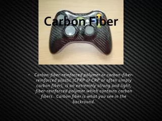
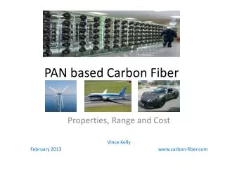
Carbon Fiber Mesh. Carbon Fiber Mesh developed by ESLI Mesh is composed of a network of carbon fibers crisscross linked into a matrix that is mostly empty space. 200 times thicker than the thinnest solar sail material, but so porous that it ways the same.

E N D
Carbon Fiber Mesh • Carbon Fiber Mesh developed by ESLI • Mesh is composed of a network of carbon fibers crisscross linked into a matrix that is mostly empty space. • 200 times thicker than the thinnest solar sail material, but so porous that it ways the same
Problems with Traditional Solar Sail Materials • Tear easy, require heavy support structure to stretch them out and keep tensioned, and can build up static electricity, and UV degrades and melt at high temps.
Why Carbon Fiber Mesh is an Ideal Choice • Can tolerate temps as high as 4,500 deg F • Small areal mass density and are immune to UV degredation. 30μm compared to 2μm with same area density (~5g/m^2) • Ability to self-deploy, the carbon scrub-pad material could be packed so it pops out flat once released. This can eliminate the need for any complicated mechanical deployment mechanism, which decrease mass of the craft. • Easier to deploy because it doesn’t cling or wrinkle • Higher Melting Point
Carbon Fiber vs. Traditional Material Forces Aluminum Coated Mylar Carbon Fiber Using sample microtruss which is formed from perfectly electrical conducting (PEC) wires. The time-average force on the sail can be found using physical optics assuming microtruss is illuminated by a uniform plane wave (UPW) and Force at 0.48AU = 0.348N
CP1 Solar Sail Material • Developed by SRS Technologies created a 5 micro meter thick film constructed of CP1 with an aluminized front surface and a black emissive black surface. • CP1 is a unique polymer which has favorable structural characteristics. Source: Scalable Solar Sail Subsystem Design Considerations
Thermal Analysis of Payload Module • Found an innovative way to configure spacecraft parts which eliminate chassis, cables and connectors. • MFS (Multifunctional Structures) achieves this by using MCM (multichip modules) and dissipating its heat through a thermal core fill, and utilizing aluminum honeycomb sandwiched between 2 fiber reinforced cyanate ester composite faceplates. • This high density configuration increases payload-mass fraction and provides major weight volume and cost savings.
MFS Configuration Thermal copper strap used to transfer heat to radiator surface. Hi-K facesheets (K13C2U) Multichip Module - Specialized electronic package where multiple integrated circuits are packaged to do many jobs with one module. High Conductivity Filler Kz = 700 W/mK Aluminum Honeycomb High K Isotropic Carbon- Carbon Doubler Edge Corefill Kz
Thermal Control of MFS • In order to dissipate waste heat from the MCM along with solar energy loads on the outer skin. Rate of heat flow Effective rad environment Radiation Equation Emissivity of radiator Temp of base plate Lateral Conductance Heat flow path length Setting equal and solving for temp of baseplate yields Average radiator temp Cross sectional area Material thermal conductivity
Thermal Control Configuration Options For MFS Integration Incorporate Thermal Doubler Hi-K Corefill Kx, Ky > 150-1500 W/mK; Kz> 40-700 W/mK High Conductivity Composite Facesheet With Kx,Ky> 150 W/mK Incorporate Heat Pipes Incorporate Deployable Radiator Where, Source: Thermal Management For Multifunctional Structures
Confirmation of MFS • The Multifunctional Structure was successful based on the data returned from the Deep Space 1 mission. This mission the MFS was tested by powering it up once every two weeks which provided a data set containing health and status information, electrical-conductivity test data, and thermal-gradient measurements. The thermal-gradient data proved to stay within operating conditions.
Thermal Analysis of Boom Supports • Carbon fiber booms need to maintain temperatures below 40 deg C. • To achieve this a coating will be applied to the outside of the carbon fiber. • By using the radiation equation and basic thermodynamics the required coefficient of absorbtivity, emmisivity can be found that satisfy these constraints. From these coefficients a coating can be chosen.
Thermal Properties of Carbon Fiber Boom. R Setting equal to each other and solving for temperature of the surface of the boom yields: Carbon fiber properties: R=13 cm Thickness = .25mm Length = 72 m K = 400 W/m Density = 1490 kg/m^3
Material Selection for Boom By graphing different values of absortivity and emmisivity the proper coating can be found that will keep the boom under 313K. White Paint (S13G-LO) with , gives T =252K
Future Work • I plan on further investigating and analyzing the spacecraft components such as the fuel tank, additional thermal control methods, and complete analysis of MFS integration into the spacecraft configuration. • Also working together with orbit group to run simulations with Aluminized Mylar, Kapton and Carbon Fiber solar sail and find best material for our mission.