Download
1 / 73
770 likes | 977 Vues
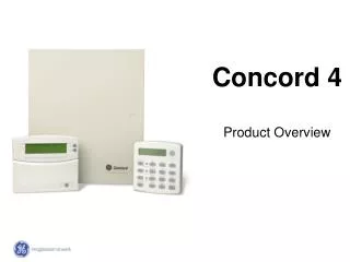
Concord 4 Security System Advanced Training. Please Silence Cell Phones and Pagers. Thanks!. Class Objectives. Upon completion of the course the trainee will be able to: Plan Install Program Test Troubleshoot Operate A basic system. (Assessment Test at end of course).

E N D
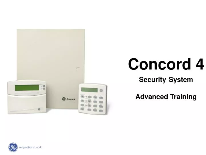
Concord 4 SecuritySystem Advanced Training
Class Objectives • Upon completion of the course the trainee will be able to: • Plan • Install • Program • Test • Troubleshoot • Operate • A basic system. • (Assessment Test at end of course)
Concord 4 Series Security Systems • Concord 4 Integrated – 600-1021-95R • Concord 4 Commercial – 600-1040
Concord Line Feature Set Wireless Hardwire Two-Wire loop 2 amps power Siren Driver Siren Driver Latchkey Chime Keyswitch arming Scheduling Outputs Status voice Home automation Cell backup Phone control Light control Activity timer TP panics Dialer delay Duress Auto stay arm Two-way voice Daylight savings Dealer code Dial tone detect Open/Close Phone test Pager support Installer code Partitions Exit extension Siren supervision Phone panics Quick arm Sleep delay CID/SIA Jam Detect Program report SnapCard Recent closing Swinger shutdown PC download Alarm verify Battery test
Concord 4 Concord 4 and Commercial Feature 96 (8 onboard) 6 Partitions 230 Users 2 Plus 1 Siren Driver 16 Bus Devices 12VDC at 1 amp Max Zones Partitions Users Outputs # Bus Devices Power Output
How to build a system Zone Expansion 8Z Input SnapCard 4 Relay Output SnapCard Output Expansion 2X16 LCD’s 2X20 LCD/VFD Fixed English Touchpads Phone Interface/Voice Energy Saver Wireless Gateway Automation Cell Backup Two-Way Voice Voice Misc. Modules
2X20 VFD Display (60-804-04) 2X20 LCD Display (60-803-04) Touchpads – All Bus Devices Fixed English Display (60-820) Fixed English Display FTP-1000) 2X16 LCD ATP 2600 Touch screen GTS 50 2X16 LCD ATP 2100 2X16 LCD Display (60-746-01) LCD Display ATP 1000
Bus Module Installation • 16 Total Bus Devices, Auto Addressing • Connections made at panel or from another bus module • Connect using Star, Daisy Chain, or Homerun configurations Star Daisy Chain Homerun
Power-Up Procedure • Connect back-up battery • Verify wiring (no loose strands) • Connect transformer to panel • Plug transformer into a non-switched outlet. • No power switch, panel will power up
Initial Power-up • Auto-addressing of all SuperBus 2000 devices wired to the panel • LCD and VFD Touchpads display “Scanning Bus Devices” • FED Touchpad displays “Bus Scan” • If nothing displays, verify wiring and correct bus device Scanning Bus Devices
Codes • Installer Code - (4321) • enter system programming • Cannot be deleted from panel • Dealer Code - (****) • protects CS phone numbers, dealer code • Downloader Code - (12345) • Must match in Toolbox as well (Account #, and Dealer Code also!) • System Master - (1234) • User programming, system operation
Programming • A LCD or VFD Touchpad must be use for programming (No FED) • Programming header on-board to allow programming at the panel • Only one Touchpad can be used for programming at a time
BUS SCAN… • A BUS scan can occur the following 4 ways… • 1. Power Up • 2. Memory Clear • 3. Manually (0+1) • 4. Download Scanning Bus Devices
Program Header Touchpad Beep • Follow this step only if the touchpad you are programming from is not staying on the system. (Fixed English Touchpad) • 8 + Installer Code (4321) + 0 + 2 • You will hear a confirmation “beep” letting you know your service touchpad is active SAT JAN 01 12:00 PM P1
Programming • Enter System Programming… • 8 + Installer Code (4321) + 0 + 0 • Touchpad displays “System Programming” • Clear Memory… • Use “B” key to scroll to “Clear Memory”, hit “#” to accept followed by Installer Code “4321, #”. SYSTEM PROGRAMMING CLEAR MEMORY
Programming “Hints” • “#” selects menu item or data entry • “*” deselects menu item or data entry • “A”&”B” scroll through available menu options • “C” enters pauses in phone numbers • “D” deletes certain settings • “1”&”2” off and on • “1-6” press and hold to enter letters A-F in account numbers • “7”&”9” * and # in phone numbers SYSTEM PROGRAMMING
Navigating • Two methods to navigate through system programming… • Flowchart Method • Shortcut Method SYSTEM PROGRAMMING
Shortcut Method • Simply enter shortcut number to jump to program item • Shortcut numbers can only be entered from a tier location • Shortcut numbers located in flowchart boxes SHORTCUT 0135
Simplify Programming • Review program shortcut listings and verify which settings need to be changed from defaults • Create a program quick guide using shortcut numbers • Use the system planning worksheets in the installation manual Enter System Programming 8 + 4321 + 00 Central Station Phone Number 01000 + Number + # + * + * + * Central Station Account Number 0010 + Number + # + * + * + * Exit Delay Time to 90 Seconds 0011 + 090 + # + * + * + * Exit Program Mode * + * + * + * + A + #
Sensor/Zone Programming • A zone is an individually identifiable point of input to the system. • Hybrid control panel (hardwire, wireless) • Zones are partition specific • Any zone can be either RF or hardwire, normally open or closed • Zone terms: • Trip Supervised • Restoral Type
Factory Pre-Programmed Zones The Concord Control Panels provide pre-programmed hardwire zones for ease of programming.
Sensor Groups SENSOR GROUP 10 • Sensor Group (Type) Number • Specific number used to tell the panel how to react when it hears a sensor activation • Commonly used Groups • 01 Key Fobs, RF Touchpads • 10 Entry/Exit Delays • 13 Perimeter Instant • 17 Motion Detector • 25 Special Chime • 26 Fire Detectors
Edit Sensors • Allows the changing of a sensors group number without deleting • Use Edit Sensor menu to view sensor information in system S01 – Zone/Sensor Number P1 – Partition Number G13 – Sensor Group Number NC – Normally Closed HW – Hardwired Back Door – Sensor Text RF – Wireless Sensor TP – Touchpad NO – Normally Open S01 P1 G13 NC HW BACK DOOR
Sensor Text • Only LCD and VFD Touchpads can display specific sensor text. • Concord PIV will speak all words from 3-digit library • Use Toolbox (PC Downloader) for larger systems SN 1 ITEM 0 050 - DOOR
Sensor Text • 16 Item Numbers per sensor (0-15) • If a word is in the library, it only takes up one item number • If using custom words (not in the library), each letter takes up one item number • Remember to include a “space” (#221) between custom words • “000” deletes item numbers SN 1 ITEM 2 006 - ALARM
Output Programming • Concord - 2 on-board open collector outputs • Outputs are programmed using a 5 digit number i.e. 01400 • First 3 digits are the trigger (what needs to happen for the output to activate) • Second 2 digits are the response time (how long the output is activated for)
Output Programming CONFIGURATION 01400 • First 3 digits are the trigger (what needs to happen for the output to activate) • Second 2 digits are the response time (how long the output is activated for) Keychain Touchpad Star Button activating an output
Programming Exercise • Enter Quick Programming Menu • Acct # 98AC2 • Phone 9 (pause) 18005551555 • Learn Zones • 1 – Group 10 • 2 – Group 13 • 3 – Group 17 • 4 – Group 26
Programming Exercise • Program hardwire zone as a Keyswitch • System should arm when zone tripped and disarm when restored
Programming Exercise • Set system to dial Central Station phone number 1 for alarms only • Set system to dial Central Station phone number 2 for trouble conditions • Set pager 1 to receive messages for alarms only
Programming Exercise • Create the following outputs • Light a red LED when the system is armed and a green LED when the system is disarmed • Open overhead garage door when star button is pressed on the keychain touchpad • Create a LED that follows the system status (off when system not ready) • Setup a motion detector that releases a door when activated (RTE)
Testing the System • A system should be tested after initial install, whenever new equipment is added, after any service work. • The following tests are available: • Zone/Sensor Test • Phone/Communication Test
Zone/Sensor Test – (8 + CODE + 3) • Which code is used to enter zone test makes a difference how the system reacts • Installer Code – Provides full wireless signal strength testing • Master Code – Provides a single beep to confirm device operation
Zone/Sensor Test – (8 + CODE + 3) • Before testing zones the installation site should be setup in a everyday situation • Close doors,windows, and cover motion detectors • Document sensor testing information for future reference if troubles should arise • Test each device and verify a passing signal is received
Sensor Test • 8 + 4321 (Installer Code) + 3 • Trip all sensors in the system, as devices are tested they are removed from memory • Listen for an acknowledgement tone for each sensor if a low tone is heard retest sensor and verify proper location
Zone Test – Concord Systems • Pass/Fail Test • During a Dealer Sensor Test the strength of the receiver is lowered to ensure during normal operation signals are heard • When a wireless or hardwire device is tripped during the test a pass or fail signal will be announced
Communication Test • 8 + 1234 (Master Code) + 2 • The system calls the Central Station and verifies proper communications Phone Test
Communication Test – 8 + Master Code + 2 • Before initiating test contact Central Station • Display reads “Phone Test” allow at least 2-3 minutes for completion of test • If after 3 attempts the Central Station is not reached a failure message will appear • Verify Phone Number • Verify Phone System • Verify Dialing Method • Verify Phone Wiring
Testing • Outputs – verify proper operation of outputs • Sirens – Trip[ alarm and verify proper siren operation • Light Control – Using touchpads turn light on and off • Verify system arms and disarms with all available codes
Troubleshooting • Have the proper tools • Eliminate the panel first • Verify programming options if communication errors • Utilize Toolbox to check event buffer • Do not clear memory before calling Tech Support 1-888-GE Security
Trouble Beeps • Sounded at hardwired touchpads, and through interior sirens • Silenced by pressing the Status key located on the touchpad (only silenced for 10 hours if the trouble is not fixed) • Initially sound at the S-Time or immediately if a specific option is turned on. • If the system is armed trouble beeps will not sound from 10pm to 8am.
AC Power Failure Low Battery Sensor Supervisory Sensor Trouble Sensor Low Battery Sensor Tamper Phone Failure Trouble Receiver Failure Receiver Interference Memory Failure Auxiliary Phone Trouble Bus Failure Unit # Trouble Conditions