Download

1 / 26
410 likes | 721 Vues
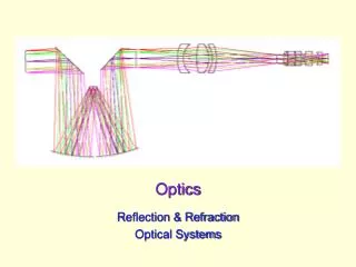
Flexures for Optics. Outline. Brief overviews of micro flexures Focus on macro flexures in this tutorial Beam bending Symmetry -> precision Degree of freedom (DOF) Applications. Micro Flexures. Tip-tilt mirrors discrete vs analog. Comb drive. Optical MEMS devices.

E N D
Outline • Brief overviews of micro flexures • Focus on macro flexures in this tutorial • Beam bending • Symmetry -> precision • Degree of freedom (DOF) • Applications
Micro Flexures Tip-tilt mirrors discrete vs analog Comb drive
Optical MEMS devices Resonant frequency of the comb drive depends on the ions hitting the pads Analog tip-tilt mirror
Motivation • Need nanometer precision to manipulate light. • “Stage” and “driving mechanism”. • Sticktion is a problem encountered with screw-type driving mechanisms. • Use piezoelectric, capacitive, magnetic, photon,… to drive the “stage”.
Symmetry in 2D • In-plane rotation • Parasitic motion not di-coupled • As soon as the stage moved, Fx developed some “local” y component • In-plane rotation minimized • Parasitic motion reduced or cancelled • Less cross-talk
Parallelogram • In-plane rotation constrained • Parasitic motion reduced • As soon as the stage moved, Fx developed some “local” y component • In-plane rotation constrained • Parasitic motion further reduced or cancelled • Less cross-talk
Deformation Diagram X/Y forces + X/Y moments
5 DOF – Pentaflex • Combination of vertical and horizontal blades • X/Y/Z translation + X/Y rotation
Highly Symmetric XY Stages Can be made into XYZ stages by adding the horizontal blades like Pentaflex Three different anchoring geometries
Diaphragm Flexures Provide out-of-plane (z,f,g) motions Constrain the other in-plane (x,y,q) motions (Voice-coil, pressure sensor, flow control, MEMS devices)
6-axis (nano) Flexures mHexFlex
q Flexures Only allows q DOF, all others conflict.
Tip-tilt Flexures Remove axial misalignment between two parts (shear), but does not remove torque/moment.
In-plane 1D Flexure In-plane 1D flexure Symmetric dual 4-bar linkage eliminates dY errror Out-of-plane 1D flexure
XYZ Translation Stage Conflict for all qfg DOF’s
Bi-stable Flexure Actuation force causes deflection Open/close a valve at some pressure threshold; on/off Have negative stiffness in the unstable region
Non-linear Spring Constant Shape -> deflection -> variable stiffness
Physik Instrument Piezoelectric drive + capacitive sensor, feedback loop to actively take out platform vibrations
Conclusion • Use flexure to avoid sticksion. • Use symmetry to cancel/de-couple motions. • In-plane vs out-of-plane configurations • Flexures for translation, rotation, and any combination of DOF (1-6 DOF). • Dynamic range and linearity. • Soft flexure -> low resonant frequency, stiff flexure -> high actuation force. • References: see FlexureForOptics.doc