Download
1 / 29
290 likes | 419 Vues
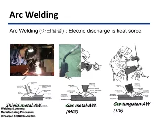
Scaling of the Cathode Region of a Long GTA Welding Arc. P. F. Mendez, M. A. Ramirez G. Trápaga, T. W. Eagar Massachusetts Institute of Technology August 23, 2000. Motivation. The arc is an essential component of a math model of the welding process

E N D
Scaling of the Cathode Region of a Long GTA Welding Arc P. F. Mendez, M. A. Ramirez G. Trápaga, T. W. Eagar Massachusetts Institute of Technology August 23, 2000
Motivation • The arc is an essential component of a math model of the welding process • The generalization of the numerical results is desirable for the interpretation and transmission of the findings • These two seemingly different motivations will be addressed simultaneously. • Emphasis will be put on generalization instead of details of the numerical solutions
Evolution of Arc Modeling • As the complexity of the model increases, the characterization of the model requires exponentially more points
Evolution of Arc Modeling • Modeling restrictions have been removed gradually • The increase in complexity focused more on the physics than on the geometry • Not all the parameters that describe the problem are simultaneously relevant • The problem can be divided in different regimes in which different sets of parameters balance each other • In each regime the description of the problem is very simple
Order of Magnitude Scaling (OMS) • Determines dominant and balancing forces (without solving the PDE’s) • Determines the range of validity of a particular balance • Provides order of magnitude estimations of the solutions • Ranks the relative importance of the dimensionless groups • Permits the construction of universal maps of a process
Formulation of the problem • Cathode region: • e.m. forces generate pressure • pressure generates momentum • no interaction with anode region • little temperature variations
Temperature variations in the cathode region Hsu, 1983 Ramirez, 1999 200 A, 10 mm, Argon
Unknown functions: Governing Equations continuity Navier-Stokes Maxwell
Problem Parameters • The parameters that completely describe the problem as formulated are: • r : density of the plasma (at max. temperature) • m : viscosity of the plasma (at max. temperature) • m0 : permeability of vacuum • Rc : cathode radius • Jc:cathode density • Ra : anode radius • h : arc length
Boundary Conditions • For the numerical model: I J
Boundary Conditions • For Order of Magnitude Scaling: unknown characteristic values
7 F E 40 H G 85 256 Behavior of the solutions BC for order of OMS Real values (200 A, 10 mm) VZ VZ VZ 40 7 E F 256 VZ 85 H G
Scaling functions • For the electromagnetic field unknown characteristic value
Scaling functions • For the fluid flow unknown characteristic values
Modified Dominant Balance • If: • unknown functions vary smoothly • normalization is performed • The dominant and balancing forces can be determined without solving the differential equation
Modified Dominant Balance • Dominant: • Radial inertial forces • Axial inertial forces • Balancing • Radial pressure variation • Radial e.m. forces • Axial pressure variation
Estimations of the characteristic parameters • Based on the balance obtained: Power-law expressions
Dimensional Analysis • The dimensionless groups that govern the model are(show both natural and imposed dim groups)
h/Rc Typical welding arc 10 1 102 Re Range of Validity • Since the coefficients in the normalized equations are the ratio of secondary forces to the dominant, the boundary between limiting cases can be defined when they are 1
Corrections for the Estimations • The differences between the estimations and numerical calculations depend only on the governing dimensionless groups • Considering only the more relevant dimensionless groups usually is accurate enough
Corrections for the Estimations • Power laws are convenient expressions • The small exponents indicate that the estimations capture most of the behavior of the model
correction function actual difference Corrections for the Estimations
Universal Process Maps • Characteristic values are scaled and corrected universal maps of the process can be build • based only on the problem parameters • no need for empirical measurements (e.g. to get maximum velocity from numerical model or experiment)
Universal Process Maps VR(R,Z)/VRS 200 A 10 mm 2160 A 70 mm
Discussion • The estimations obtained are comparable to those available in the literature (Maecker 1955) • Accuracy of the estimations can be increased by using • numerical results or experiments • relevant dimensionless groups • The effect of simplifications (e.g. constant properties appear as error in the correction functions) • The contour maps suggest ways of improving the numerical model • In sharper electrodes the e.m. forces also generate momentum without increase in pressure • application to GMAW?
Discussion • Is there a unique solution to the dominant balance? • Can dominant balance be fooled? • Does normalization solve potential paradoxes in dominant balance?
Conclusions • Viscous effects are small • Electromagnetic forces create pressure, which is balanced by inertial forces • thermal expansion is secondary • Power-law form equations, based only on the parameters of the problem provide: • properties of the fluid flow • correction functions • Universal maps of the arc can be generated • they can be scaled to a wide range of arcs
State of the Art in Arc Modeling ELECTRODE BEHAVIOR Morrow & Lowke.1993. 1D theory for Delalondre & Simonin.1990. 1D. Chen, David, Zacharia, 1997 CATHODE AND ANODE FALLS the electric sheats of electric arcs. (anode modeling high intensity arcs inclu- model interaction between the and cathode falls). ding non equilibrium description of and the weld pool in GTA. Free the cathode sheath. surface changing with time 2AA Zhu & Lowke.1992. Treats cathode Kim, Fan, Na. 1997. 2D boundary layer and arc column as Auttukhov, 1983 Chen & Zacharia, 1991. GTA, cathode influence unified system. Current thermionic emission Analysis of the electrode tip and free surface. No angle and geometry of the assumption on Jc. Tekriwal, Mazunder.1988.2D analytical 2AC GTA weld pool. Mckelliget & Szekely.1986 Cram, 1983. Focussing model for heat source (pointed tip). Choo, 1990. Couple between cathode and anode on the energy balance of Convection at anode by means of heat arc and weld pool. Deformation development the electrode transfer coefficient, properties constant Sui & Kou, 1990. 2D, of the pool. Effect of the tip geometry 2AB Hsu & Pfender,1983. Detailed shielding gas, nozzle, model for the cathode region Westhoff, 1989. 2D arc model 2A specifying current density at anode. 2C deformation of weld pool. Small changes in Jc changes T fields. Dawson, Bendzak, Mueller, 1997 Pradip, Yogadra, Rama, 1995 Fluid flow and Heat Transfer in a 3D, heat transfer, fluid flow in GTAW twin cathode DC furnace. Exp. with non-axisymetric b.c.’s. Maxwell 2B messurments in lab. modeling furnace equations, uses buoyancy, surface tension and electromagnetic forces. ARC COLUMN MODELING Qian, Farouk, Mathasaran, 1995 McKelliget & Szekely, 1986. 2D, DC approximate BASED ON PHYSICAL PRINC. Fluid flow and heat transfer in boundary conditions. Jc=65MA/m 2 B.C.’S APPROXIMATED OR EAF, 2D, DC EAF WELDING EXP. DETERMINED. Goldak & Moore. 1986. Finite ele- ment method. Describes the source. McKelliget & Szekely, 1983 Kovitya & Cram, 1986. 2D, LTE 2D arc model, coupling pool MHD, boundary conditions assumed. Lowke 1980. 2D continuity and arc models. Kovitya & Lowke, 1985. 2D, uses energy, naturla convection. properties theoretically calculated. Hsu, Etemadi, Pfender, 1983. 2D Jc=100MA/m . Extends Lowke’s 2 2 MHD eqs. with b.c’s experimentally McKelliget & Swzekely, 1981. RF DISCHARGES ,odel to incorporate Lorentz’s for- determined. Anode and cathode Heat transfer & Fluid flow in ces and electron drift enthalpy. excluded. Jc assumed with a gaussian a EAF shape. Allum, 1981. 2D Assumes current Ramakrishan & Nou. 1980. and velocity in gaussian profiles. Dinulesca & Pfender, 1980 lowke, 1979. 2d momentum and en 3 1 2D, semianalytical model. Includes magnetic, viscous and Analysis of the boundary ergy eqs. Natural convection. Radial vel. field assumed. gravitational forces. layer in high intensity arcs Low currents. Lowke, 1979. 1D, analytical Chang, Eagar, Szekely. 1979. Velo- model for arc voltage, electric city fields calculated analytically Ushio, Szekely, Chang, 1980 field and plasma velocity. using Lorentz’s forces. 2D model, assuming parabolic Glickstein, 1979. 1D, analytical. Radial current density distribution, variations of temperature and J. No plas- k-e turbulent model. ma flow. Squire 51: isothermal, point force Maecker 55: e.m. force approx Shercliff 69: point current Yas’ko 69: dimensional analysis 1=RF Discharges (nat. convection). 2=Welding (Laminar flow). 3=EAF (turbulent flow). 2A=B.C.(anode and cathode modeling) 2B=Coupled arc and weld pool (welding) 2C=Geometry effects in welding. 2AA=ANODE REGION 2AB= ANODE AND CATHODE 2AC=CATHODE REGION