Download
1 / 27
280 likes | 576 Vues
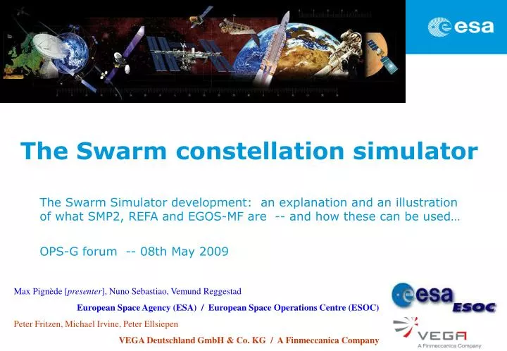
The Swarm constellation simulator. The Swarm Simulator development: an explanation and an illustration of what SMP2, REFA and EGOS-MF are -- and how these can be used… OPS-G forum -- 08th May 2009. Max Pignède [ presenter ], Nuno Sebastiao, Vemund Reggestad

E N D
TheSwarmconstellation simulator The Swarm Simulator development: an explanation and an illustration of what SMP2, REFA and EGOS-MF are -- and how these can be used… OPS-G forum -- 08th May 2009 Max Pignède [presenter], Nuno Sebastiao, Vemund Reggestad European Space Agency (ESA) / European Space Operations Centre (ESOC) Peter Fritzen, Michael Irvine, Peter Ellsiepen VEGA Deutschland GmbH & Co. KG / A Finmeccanica Company
What this presentation is about… • Why attempting a new approach in making simulator software ? • Explanation of what SMP2, REFA and EGOS-MF are • Illustration of how SMP2, REFA and EGOS-MF are applied for the Swarm Simulator development in the SIMSAT 4 environment • Conclusions -- then Q&A OPS-G forum | The Swarmconstellation simulator development | 08th May 2009 | Slide2
Rationale -- Background • Recognition that development strategies better than mere reuse should be explored • Take advantage of new technologies and of ESA most recent standards • ESOC is preparing the first deployment of a new generation of operational simulators in the context of the Swarm mission, a constellation of three satellites more details available at http://www.esa.int/esaLP/LPswarm.html OPS-G forum | The Swarmconstellation simulator development | 08th May 2009 | Slide3
CDMU AOCS SDB Generic Models Power Payloads RFCS Thermal Why do we need a reference architecture ? Example of what a simulator software architecture may look like: • No clear interface between models • Difficult to isolate models for reuse • Transforming a working simulator into a new one can result in a faulty simulator and cause much unneeded code to stay • Reuse potential mostly only via “copy&paste” How about if we … • defined clear interfaces between the different elements in a spacecraft ? • defined some suitable breakdown of a whole simulator into models ? • improved reusability at model level in a “plug&play” fashion ? OPS-G forum | The Swarmconstellation simulator development | 08th May 2009 | Slide4
“Operationally responsive” technologies • The SMP2 Standard … • promotes portability of models among different simulation environments and operating systems • promotes the reuse of simulation models • fulfills these objectives by providing a standard interface between the simulation environment and the models • The Reference Architecture (REFA) … • identifies, using SMP2, a reference spacecraft simulator architecture which can be used as the basis for simulators design and development • achieves shorter development cycles by reuse relying extensively on a common architecture • fulfills these objectives by specifying interfaces between spacecraft subsystems and by identifying models which can be developed in a generic fashion OPS-G forum | The Swarmconstellation simulator development | 08th May 2009 | Slide5
SMP2 architecture SMP2 first component: a SIMULATION (with its model instances) … … Model.1 Model.2 Model.i Model.n Mandatory services: Information logging Entry point scheduling Times provision Events manager Mandatory interfaces: Access to simulator state Access to simulator services Publication mechanism The interface offered by the simulation environment to the model does not change Models interact with each other Schedule calls model entry points Models call any simulation service SMP2 second component: a Simulation ENVIRONMENT (and its services) ` The interface offered by the model to the simulation environment does not change OPS-G forum | The Swarmconstellation simulator development | 08th May 2009 | Slide6
Model IModel Simulation Environment ISimulator IService IScheduler Scheduler ITimeKeeper Time Keeper ILogger Logger IEventManager Event Manager SMP2 simulation services and interfaces • Simulation services are … • provided by the simulation environment • consumed by the models • based on standardised interfaces Connect Run Hold Restore GetState GetTimeKeeper GetModel …etc… Connect Configure Publish GetName GetParent …etc… • Every model must implement the IModel interface • Every simulation service must implement the IService interface OPS-G forum | The Swarmconstellation simulator development | 08th May 2009 | Slide7
Catalogue C1 Assembly A2 Model M1 Model-Instance C Fields .. Operation .. Association .. Model M2 Assembly A1 Model-Instance A Model M2 Schedule S1 Field .. Associations .. Entry Point .. Model M1 Model M3 Assembly A3 Assembly A1 Model-Instance B Model M3 Model M1 Model M4 Model M3 Fields .. Entry Points .. SMP2 hierarchy -- the main parts The Assembly translates into the Simulation tree at the MMI and can hold the initial values of fields The Simulation Model Definition Language (SMDL) defines the format of all these XML files Catalogues define SMP2 models library Schedules define the scheduling of the entry points of model instances Assemblies specify how model instances are integrated For example, if the Schedule calls an <<SMP2entryPoint>>+Update() of a Thermistor model, a temperature will be retrieved from some thermal node and this will result in an update of the temperature measured by the Thermistor OPS-G forum | The Swarmconstellation simulator development | 08th May 2009 | Slide8
SMP2 key benefits • SMP2 avoids developing models which use the operating system or hardware specific dependencies -- Platform Independent Model (PIM) • SMP2 promotes the use of modern software engineering techniques -- in particular component based design • SMP2 makes reuse easier via breaking dependencies between simulator models • SMP2 allows dynamic configuration -- for example the user may at “runtime”: • select different orbit propagators depending on the required accuracy • switch a component that simulates a hardware equipment with a component that interfaces with the real equipment (e.g. when moving from models to real checkout devices) SMP2 is a ESA standard evolving into an ECSS standard to standardise SMP2 more widely under the ECSS umbrella to take this opportunity for enhancing SMP2 version 1.2 (e.g. support of dynamic models, initialisation of model parameter values) OPS-G forum | The Swarmconstellation simulator development | 08th May 2009 | Slide9
REFA onset • REFA started with investigating what would be worth being standardised for all satellite subsystems across simulators -- via the actual screening of 4 different space missions • As a result REFA identified … • what should the “reference spacecraft simulator” requirements be • all interfaces between the different elements in a spacecraft simulator • the models which can be developed • in a generic fashion (e.g. satellite dynamics, orbital environment modelling, satellite thermal control, communications subsystem, …) • those other models which need to be developed specifically for each mission • This is a system architecture -- some work remains to be done ... • Use this architecture as the basis for future simulators development ! OPS-G forum | The Swarmconstellation simulator development | 08th May 2009 | Slide10
REFA subsystems: Payloads Electrical Power AOCS Data Handling Radio Frequency Thermal Control Reaction Control Data Links REFA utilities Simulation Monitor Parameter Mapper Configurator Generic Units Parameters Events Failures Messages Aligned Unit Simulation Model Portability 2 (SMP2) Component Model Magnetic Torquer Head Logger Scheduler Time Keeper Resolver Events Manager REFA logical model REFA … is a system architecture (only) and not a reusable implementation of satellite models provides also a generic implementation for some models, e.g. Powered Units, Model parameters OPS-G forum | The Swarmconstellation simulator development | 08th May 2009 | Slide11
Aligned Unit Generic Models (SMP2) Magnetic Torquer Interface External Force Interface SIMDYN Magnetic Torquer Head External Force Earth Magnetic Field Interface PEM Earth MagneticField REFA output Illustrated via the AOCS example of the Magnetic Torquer Head … Interface allowing to set the dipole momentum and to read the produced torque The Magnetic Torquer Head requires an interface to read the Earth Magnetic Field The Magnetic Torquer Head requires an interface to provide an External Torque OPS-G forum | The Swarmconstellation simulator development | 08th May 2009 | Slide12
REFA actual use in a project Example of … Swarm::Aocs::MagneticTorquerHead inherited directly from … REFA::Aocs::MagneticTorquerHead REFA model -- shown in previous slide … Swarm model -- derived from a REFA model to provide the mission required implementation OPS-G forum | The Swarmconstellation simulator development | 08th May 2009 | Slide13
EPS TCS RFCS Battery PCDU Solar Array Thermistor Thermostat Solar Surface Antenna Combiner Transfer Switch Transmitter Receiver AOCS Ground STR CESS FGM MTQ GPSR Uplink Downlink RCS Data Links Mass Flow Sensor Tank Latch Valve 1553 ACARO UART ML16 DS16 Pressure Transducer Flow Control Valve Payloads Deployable ASM VFM C-EFI ACC DBA Pipe Branch Thruster Pipe Merge Colour Scheme Fully REFA Defined Partially REFA Defined DHS OBT PM RM TM MM Multi UART TCD CPDU RU Not REFA Defined REFA for building a new simulator ... OPS-G forum | The Swarmconstellation simulator development | 08th May 2009 | Slide14
REFA benefits • Models developed based on REFA are potential candidates for later reuse in other simulators. Therefore … • all components need a complete documentation of their interfaces • and this documentation must be alwayssynchronisedwith the actual implementation • hence source code and documentation must originate from a single source • The reuse of existing mechanisms, infrastructurecomponents and base models will result in a more harmonisedbehaviour ofoperational simulators, such as … • same user commands between simulators • identical tracing, logging, reporting characteristics on different simulators • Overall increased productivity in the development of new simulators OPS-G forum | The Swarmconstellation simulator development | 08th May 2009 | Slide15
EGOS Modelling Framework (EGOS-MF) • Eclipse based IDE extension for developing SMP2 simulators and for increasing software development efficiency • EGOS-MF is a collection of Eclipse Plug-ins. • It uses MagicDraw integrated into Eclipse. • Supports the full life cycle of simulator development • design of models -- systematically (re-)start at the UML design stage ! • code generation by SIMSAT MIE (including code merge) • document generation (with customisation of generation templates) • model execution and debugging • The answer for managing simulators complexity efficiently is … • to model ! -- and the model is the single source of information • to automate ! • and not to repeat yourself ! • Hence: Model Driven Software Development (MDSD) supported by the EGOS-MF suite OPS-G forum | The Swarmconstellation simulator development | 08th May 2009 | Slide16
How to apply MDSD using UML and EGOS-MF ? • This process will be updated based on the Universal Modelling Framework (UMF) once it is available: UMF will replace EGOS-MF and SIMSAT Model Integration Environment (MIE) by a single Integrated Development Environment (IDE) which further integrates the Eclipse C++ Development Tools (CDT) and which does not need to be run within SIMSAT. • Import the simulator requirements in EGOS-MF • With the requirements in place, the design of mission specific models can be started: Example: new disk mapped memory model, using the UML modules from REFA • Create a new SMP2 Model named “DiskMappedMemory”: this will create a UML Component with the <<SMP2model>> stereotype • Drag & Drop the “Memory” model and the “IMemory” interface from “REFA/Generic/Units” onto the diagram and make the new model derive from the existing REFA model -- using the “Generalization” button OPS-G forum | The Swarmconstellation simulator development | 08th May 2009 | Slide17
when a design has been entered, it is typically needed to create a SMP2 Catalogue for it this Catalogue can then be used to generate C++ source code EGOS-MF overall development workflow SDD, ICD, SUM .... Architecture and Architecture and Interface Design Interface Design Requirements Engineering Requirements Engineering Development Development EGOS-MF profile Requirements Editor Requirements Editor Document Generation Tool Document Generation Tool doxygen doxygen .doc .html .doc .html UML Editor CORBA IDL Generation Tool CORBA IDL Generation Tool .idl .idl .csv .csv C++ Compiler C++ Compiler .cpp .cpp UML Model UML Model Requirements Import Tool Requirements Import Tool XML Schema Generation Tool XML Schema Generation Tool .xsd .xsd validation violation messages trace back to the violation location within the UML model Catalogue Import Tool Catalogue Import Tool Catalogue Generation Tool Catalogue Generation Tool C++ CodeGenerator (MIE) .cat .cat for REFA defined formats, such as Log Messages file format or TM/TC database file format (read in by the SCOS MIB Reader) Model Validation Tool Model Validation Tool Catalogue Validator (MIE) .cat .cat OPS-G forum | The Swarmconstellation simulator development | 08th May 2009 | Slide18
EGOS-MF code generation process This systematic code generation process is illustrated next, proceeding from the previous UML example <<SMP2model>>MagneticTorquerHead Models are essentially source code Design Development Catalogue Editor Editor Templates UML Model Catalogue Generation Tool SMP2 Catalogue C++ Code Compiler Object File Code Generator Catalogue Validator Package Editor SMP2 Package Makefile Linker Shared Object Platform Specific Model (PSM) OPS-G forum | The Swarmconstellation simulator development | 08th May 2009 | Slide19
EGOS-MF example: Catalogue Generation • The Catalogue Generator translates UML Design into SMP2 Catalogue (XML File) OPS-G forum | The Swarmconstellation simulator development | 08th May 2009 | Slide20
EGOS-MF example: C++ Code Generation • The Code Generator generates C++ Source Code for each SMP2 Model wih SIMSAT MIE • it converts the types defined in the Catalogue into C++ source code (header files and skeleton implementation files) • various methods (e.g. for publication and dynamic invocation) are auto generated OPS-G forum | The Swarmconstellation simulator development | 08th May 2009 | Slide21
EGOS-MF: use of the C++ Code Merger • The user-defined methods are empty and need to be completed using an external C++ development environment. • the Code Merger can merge an existing implementation into newly generated skeleton code. Therefore, all operations that already have an implementation maintain their implementation • “manual” changes do not have to be re-applied after each merge • neither SIMSAT nor EGOS-MF support implementation of model specific functionality -- beyond auto generated SMP2 code OPS-G forum | The Swarmconstellation simulator development | 08th May 2009 | Slide22
EGOS-MF example: C++ Code Merger output • portion of source code of the MagneticTorquerHead -- after merging • Illustration of the merging of the “manual” code of the “setter” for the magnetic dipole momentum which causes an update of the produced torque … • portion of auto generated code without implementation -- before merging • portion of source code of the MagneticTorquerHead -- after merging void MagneticTorquerHead::set_DipoleMomentum( ::Smp::Float64 value ) { // MARKER: OPERATION BODY: START // INSERT HERE OPERATION BODY // TODO: set the field value (the attached field was not defined in the catalogue model) //TBD = value; // MARKER: OPERATION BODY: END } // --OPENING ELEMENT--MagneticTorquerHead::set_DipoleMomentum-- /// The setter for the magnetic dipole momentum. This causes an update of the produced torque /// The produced torque is computed as cross product of the magnetic dipole momentum /// per Earth magnetic field. The produced torque is then set into SIMDYN void MagneticTorquerHead::set_DipoleMomentum( ::Smp::Float64 value ) { // MARKER: OPERATION BODY: START // Setup the coordinate systems used in the computations ::Common::Direction earthMagneticField(this->coordinateSystem); ::Common::Direction dipoleMomentumVector(this->coordinateSystem); ::Common::Direction torqeDirection(this->bodyCoordinateSystem); this->dipoleMomentum = value; dipoleMomentumVector = this->pointing * this->dipoleMomentum; earthMagneticField = _EarthField->At(0)->get_MagneticField(); torqeDirection = dipoleMomentumVector.CrossProduct(earthMagneticField); this->torque = torqeDirection.GetAsArray(); _ExternalForce->At(0)->set_Torque(this->torque); // MARKER: OPERATION BODY: END } // --CLOSING ELEMENT--MagneticTorquerHead::set_DipoleMomentum-- OPS-G forum | The Swarmconstellation simulator development | 08th May 2009 | Slide23
SWARM SDD REFA SDD SWARM SDD EGOS-MF example: Document Generation • The Document Generator generates Design Documentation for each SMP2 Model OPS-G forum | The Swarmconstellation simulator development | 08th May 2009 | Slide24
Drag and drop directly from tree to display window Users common views across simulators • Users have identical views on … (for example): • Message logging filtering • Model failures • Parameter limits • Simulation tree (defined in the Assembly) • Users have identical views (for example) on failed or forced parameters: • The magnetic torquer head has Analogue Parameters (e.g. the global magnetic field) -- hence they have limits and they can be forced • The magnetic torquer head can be failed because it is a Generic Unit OPS-G forum | The Swarmconstellation simulator development | 08th May 2009 | Slide25
Conclusions • Building the ESA operational simulators is “better, faster, cheaper” with: • SMP2 -- interfaces enabling reuse and exchange of satellite models • REFA -- structured reuse of past acquired simulators knowledge • EGOS-MF -- automatised component based development • SIMSAT -- solid software infrastructure on linux platforms • From the users perspective • These advanced technologies respond to project needs and schedules • Demonstrated potential for reduced costs in producing future simulators • Requirements for multi-satellite systems are satisfied OPS-G forum | The Swarmconstellation simulator development | 08th May 2009 | Slide26
Thankyou for your attention Any questions ? Max Pignède [presenter], Nuno Sebastiao, Vemund Reggestad European Space Agency (ESA) / European Space Operations Centre (ESOC) Peter Fritzen, Michael Irvine, Peter Ellsiepen VEGA Deutschland GmbH & Co. KG / A Finmeccanica Company