Download
1 / 16
160 likes | 522 Vues
Japan-US Workshop on Fusion Power Plants and Related Advanced technologies with Participation of EU Jan. 11-13, 2005. Impact of Fusion Reactor on Electricity Grids Yasushi Yamamoto, Satoshi Konishi Institute of Advanced Energy, Kyoto University. Nuclear Fusion Reactor.

E N D
Japan-US Workshop on Fusion Power Plants and Related Advanced technologies with Participation of EU Jan. 11-13, 2005 Impact of Fusion Reactor on Electricity GridsYasushi Yamamoto, Satoshi KonishiInstitute of Advanced Energy, Kyoto University
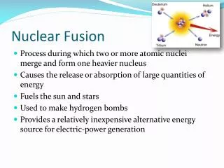
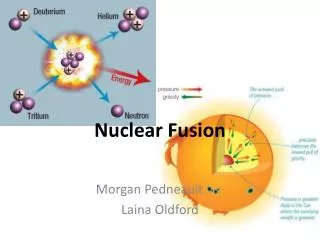
Nuclear Fusion Reactor Nuclear fusion reactor is one of candidates for sustainable energy source in the future without carbon dioxide emission. In conceptual studies, fusion reactor is assumed to be used as a base load machine in industrial countries with unit capacity of > 1GWe, • continuous operation with maximum power • > 200MWe startup/operation power Startup scenario with inductive current drive requires very large dP/dt value and large Q Our question is can the fusion reactor be installed in the small electric grid ? → calculate the influence of startup power in the small electric grid
Energy flows in fusion reactor • Q=50, Pi=60MW → auxiliary power ratio = ~13% Grid Pc=Pi+Pa Pth=Pc+MPn 3372MW Pa =Pf /5 Pnet=(1-e)Pe Pn 1250MW Generator he Blanket M Plasma Q Pe=hePth Pf +Pi 1.13 0.4 MPn 1450MW 3060MW Driving System hd Pd Pcir=ePee Pi = hd Pd 120MW 200MW 60MW 0.5 Auxiliary System hanc Paux ~5% 80MW
Auxiliary power in power plants Coal Oil Nuclear Fusion Current drive / Auxiliary heating Coal crusher Tritium handing Coal feeder Oil feeding pump Magnet cooling Exhaust gas treatment system Recirculation pump Condensate water pump Cooling water pump Control system Others
Auxiliary power ratio of various system Source: 内山洋司;発電システムのライフサイクル分析,研究報告,(財)電力中央研究所(1995)
Influence to the electric grid Power demand in ITER standard operation scenario Active power P = ~300MW dP/dt = ~230MW/s Reactive power Q > 600MVA by on-site compensation Qgrid = ~ 400MVA
Influence to the electric grid • Power generation is controlled by Time scale method > ~10min ELD or manual 3min< t < 10min AFC < ~3min governor of each UNIT (spinning reserve) In Japan, usual value of spinning reserve is 3% of total generation
Influence to the power grid • Calculation model Thermal Generator 10km 100km Transmission Line Hydroelectric Generator Demand 10km Fusion Reactor Reference Capacity : 1000MVA Transmission Voltage : 115kV System capacity : 7-15GWe Impedance per 100km : 0.0023+j0.0534[p.u.] Capacitance : jY/2 = j0.1076[p.u.]
Influence to the power grid • Frequency fluctuation
Influence to the power grid • Maximum Frequency Fluctuation [Hz] for 7GW grid • Maximum Frequency Fluctuation [Hz] for 15GW grid
Influence to the power grid • The grid capacity of 10-20GW is required to supply startup power of ITER like fusion reactor. In the small grid, more than the usual value (3% of total capacity) of spinning reserve is required • The influence also depends on the grid configuration, as response time of each power unit is different.
Influence to the power grid • 8GW Grid with plant capacity ratio Nuclear:Thermal:Hydro = 28:58:14 230MW 330MW
Electric Grid in Japan Comb structure due to geographical reason Hokkaido 5,345MW 579MW Utility Name Max. demand (~2003) Largest Unit (Nuclear) DC connection 600MW Tohoku 14,489MW 825MW Hokuriku 5,508MW 540MW West Japan Grid 60Hz, ~100GW 600MW Kyushu 17,061MW 1,180MW Kansai 33,060MW 1,180MW Chubu 27,500MW 1,380MW Tokyo 64,300MW 1,356MW Chugoku 12,002MW 820MW Shikoku 5,925MW 890MW 300MW East Japan Grid 50Hz, ~80GW
Demand (GW) Hour Demand change within the day in the summer Grid capacity is almost a half of maximum at early morning
West Japan (~100GW) UCPTE(~270GW) ERCOT (~50GW) Texas Western Interconnection (~140GW) Frequency deviation from reference (mHz) Eastern Interconnection (~500GW) (min) Variation period Frequency deviation and grid capacity
Conclusion • The rate of change of active power requirement for additional heating is faster than the response time of electric grid. • For a Fusion rector with 1GWe output, the grid capacity of 10~20GWe is required for safely supplying startup power. • By develop the slower increase of additional heating power (NBI, ECH, ICRF …) and L-H transition scenario, which matches the response time of electric grids, fusion reactor can be installed into more smaller grids. • Developing above scenario also help the fusion reactor can be used as middle load plants in the countries where there are many nuclear fission reactors for base-load plants. • In current calculation, reactive power is assumed to be supplied locally. We will estimate the influence of it.