Download
1 / 37
490 likes | 965 Vues
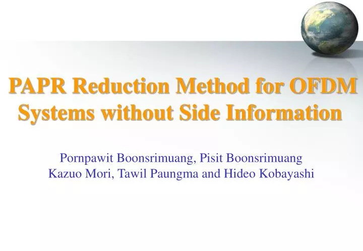
PAPR Reduction Method for OFDM Systems without Side Information. Pornpawit Boonsrimuang, Pisit Boonsrimuang Kazuo Mori, Tawil Paungma and Hideo Kobayashi. Contents. Research Topic Objective of Research Conventional Methods Proposal of PAPR Reduction Method Performance Evaluation

E N D
PAPR Reduction Method for OFDM Systems without Side Information Pornpawit Boonsrimuang, Pisit Boonsrimuang Kazuo Mori, Tawil Paungma and Hideo Kobayashi
Contents • Research Topic • Objective of Research • Conventional Methods • Proposal of PAPR Reduction Method • Performance Evaluation • Conclusions
Research Topic Proposal of PAPR Reduction Method for OFDM Signal without Side Information OFDM: Orthogonal Frequency Division Multiplexing
Target of Research Field Outdoor 100Mbit Indoor Gigabit Next Generation of Wireless LAN
Advantages of OFDM • Enable the higher data rate transmission • Robustness to multi-path fading • Efficient usage of frequency bandwidth • The OFDM has already been adopted as the standard transmission techniques in • ADSL(Asynchronous Digital Subscriber Line) • Terrestrial Digital TV • WiMAX(Worldwide Interoperability for Microwave Access) • Wireless LAN(Wireless Local Area Network) • Candidate transmission technique for the next generation of wireless LAN systems
Structure of OFDM System System Overview (a) OFDM spectrum Serial to Parallel (S/P) Parallel to Serial (P/S) s(t) ... ... Mod IFFT Add GI AMP Transmitter vs. (b) conventional FDM spectrum Fading Channel H(w) Channel Noise n(t) Receiver r(t) Parallel to Serial (P/S) Serial to Parallel (S/P) Equalization Remove GI ... ... Demod FFT Channel estimation
Disadvantage of OFDM Larger peak to averaged power ratio (PAPR) Larger PAPR will cause the degradation of BER performance and expansion of spectrum re-growth in the non-linear channel PAPR: Peak to Averaged Power Ratio
Comparison of OFDM Signal with Single Carrier Signal 2 2 1.5 1.5 1 1 Amplitude of OFDM Time Domain Signal Amplitude of OFDM Time Domain Signal 0.5 0.5 0 0 0 100 200 300 400 500 0 100 200 300 400 500 Sample Number Sample Number (a) OFDM signals in time domain (b) Single carrier signal in time domain Amplitude of OFDM time domain signal is fluctuated much larger than that for single carrier signal
4 Linear 2 r=30 r=6 0 -2 r=2 r=4 Output Power (dB) -4 -6 -8 -10 -10 -8 -6 -4 -2 0 2 4 Input Power (dB) Operation of OFDM Signal at Lower IBO in Non-Linear Channel where F[ ] represent the AM/AM conversion characteristics of non-linear amplifier
4 Linear Inter-modulation Noise 2 r=30 r=6 0 -2 r=2 r=4 Output Power (dB) -4 -6 -8 -10 -10 -8 -6 -4 -2 0 2 4 Input Power (dB) Operation of OFDM Signal at Higher IBO in Non-Linear Channel where F[ ] represent the AM/AM conversion characteristics of non-linear amplifier
Serial to Parallel (S/P) Parallel to Serial (P/S) s(t) ... ... AMP IFFT Add GI Mod Inter-Modulation Noise Occurred at Non-Linear Amplifier Transmitter structure of conventional OFDM AMP Non-Linear (b) Output of power amplifier (a) Input of power amplifier
Disadvantage of OFDM Technique OFDM with N sub carriers has PAPR ratio of 10log N [dB] N sub Carriers Larger PAPR Required Low Input Back-Off Inefficient Usage of Power Amplifier
Improvement of PAPR Several methods have been proposed to reduce the PAPR of OFDM signal • Data coding technique • The main disadvantage of this method is to degrade • transmission efficiency • Clipping technique • The main disadvantage of this method is to degrade • BER performance • Phase alignment technique • The main disadvantage of this method is required to transmit • side information which leads the degradation of transmission • efficiency
Conventional PAPR Reduction Methods Based on Phase Alignment Technique • The Selected Mapping (SLM) and Partial Transmission Sequence (PTS) methods which control the phase of data sub-carrier • SLM and PTS are required to inform the phase information to the receiver as the side information (SI) for the correct demodulation • Although the conventional method could improve the PAPR performance relatively, • the transmission efficiency and system complexity would be degraded because of the necessity of transmission of side information
Objective of Research Improve PAPR and BER performances without degradation of transmission efficiency Proposal of PAPR Reduction Method for OFDM Signal Based on Phase Alignment Technique which Requires No Side Information
Proposal of PAPR Reduction Method for OFDM Signal without Side Information • Use the common weighting factor over one frame including the preamble symbols • The time-frequency domain swapping algorithm is employed in the determination of common weighting factor • The common weighting factor can be estimated together with the channel frequency response by using preamble symbols • The common weighting factor can be removed from the received data symbols by using the frequency domain equalization Proposed method could improve the PAPR performance without Side Information
Structure of Proposed PAPR Reduction Method Weighting Factors for Reducing PAPR 1st Preamble Symbol 0 1 2 N-1 2nd Preamble Symbols Common weighting factor over one frame 1st Data Symbol One Frame Lth Data Symbol Number of sub-carriers Common weighting factor will be assigned for each sub-carrier over one frame
Determination of Weighting Factor by Using Time-Frequency Domains Swapping Algorithm Predetermined threshold level (S) FFT Amplitude (Time Domain) Amplitude (Time Domain) Frequency domain Time domain Basic concept of Time-Frequency Swapping Algorithm
mi (t) ei (t) 0 N-1 0 N-FFT N-1 N-FFT Flowchart of Time-Frequency Domains Swapping Algorithm 3 Calculation of Time-domain Signal 2 S 1 Threshold level(S) Calculation of Error Signal 2 FFT 1 Determined Phase (weighting factor)
2 1 Amplitude 0 -1 0 10 20 30 40 50 60 Sampling time Basic Concept of Proposed Algorithm 0 N-1 0 1 N-2 N-1 2 3 4 5 6 Frequency Domain IFFT S Threshold Level Time Domain
2 1 Amplitude 0 -1 0 10 20 30 40 50 60 Sampling time Basic Concept of Proposed Algorithm 0 N-1 0 1 N-2 N-1 2 3 4 5 6 Frequency Domain FFT Time Domain
2 1 Amplitude 0 -1 0 10 20 30 40 50 60 Sampling time Basic Concept of Proposed Algorithm 0 N-1 0 1 N-2 N-1 2 3 4 5 6 Frequency Domain FFT Time Domain
2 1 Amplitude 0 -1 0 10 20 30 40 50 60 Sampling time Basic Concept of Proposed Algorithm 0 N-1 0 1 N-2 N-1 2 3 4 5 6 Frequency Domain FFT Time Domain
2 1 Amplitude 0 -1 0 10 20 30 40 50 60 Sampling time Basic Concept of Proposed Algorithm 0 N-1 0 1 N-2 N-1 2 3 4 5 6 Frequency Domain IFFT Time Domain
2 1 Amplitude 0 -1 0 10 20 30 40 50 60 Sampling time Basic Concept of Proposed Algorithm 0 N-1 0 1 N-2 N-1 2 3 4 5 6 Frequency Domain FFT S Time Domain
Amplitude 3 2 1 0 Time Sample Number (a) Before T-F Swapping Algorithm 1.5 1 0.5 0 20 20 40 40 60 60 80 80 100 100 120 120 0 0 Amplitude Time Sample Number (b) After T-F Swapping Algorithm Amplitude of OFDM signal in the time domain
Determination of Weighting Factor Error signal in frequency domain OFDM signal in frequency domain Determined weighting factor Average for the weighting factors obtained for all symbols Common weighting factor over one frame
1 1 0 0 -1 -1 -1 -1 0 0 1 1 (a) (b) Scatter Diagram of Preamble and Data Symbols (a) Original OFDMSignal (b) Phase Rotation due to weighting factor
0 yk Xn T D / A ³ P S i Number of Data & F / / SSPA + GI & MOD S P F X predetermined iteration Preamble I U / C or PAPR < Target Yes No N - 1 Calculate error signal Determination of FFT common weighting factor Structure of Transmitter for Proposal Method
D / C & - GI S / P FFT P / S DEMOD DATA X ˆ A / D - 1 H n Estimation Preamble Structure of Receiver for Proposed Method Received Data Frequency Domain Equlization Estimated Channel Response Demodulated Data : Weighting Factor at n-th Sub-Carrier
List of Parameters in Performance Evaluation
PAPR Performance Modulation Method =64QAM Conventional Proposed
PAPR Performance vs. Number of Iterations Modulation Method =64QAM Conventional Proposed
BER Performance Modulation Method =16QAM Conventional Ideal Proposed
BER Performance Modulation Method =64QAM Conventional Ideal Proposed
Conclusions • Proposed the PAPR reduction method for OFDM • signal without side information • Use the common weighting factor over one frame including the preamble symbols • The time-frequency domain swapping algorithm is employed in the determination of common weighting factor • The common weighting factor can be removed from the received data symbols by using the frequency domain equalization • The common weighting factor can be estimated together with the channel frequency response by using preamble symbols
Conclusions The proposed technique can achieve the better PAPR performance and better BER performance than the conventional OFDM in the channel of non-linear amplifier and multi-path fading