Download
1 / 25
250 likes | 346 Vues
Project #6 Automated Cart. Benjamin Liu Mike Snopko. Introduction.

E N D
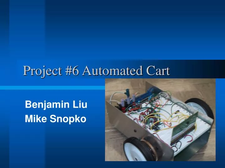
Project #6 Automated Cart Benjamin Liu Mike Snopko
Introduction • Using a stepper motor the cart will travel to a preprogrammed location by a specified path with no help from sensors. We will use a Microcontroller to direct the path for it to follow, by telling the motors which direction to rotate in order to turn the direction of the cart, and how far to travel. This could be useful in several application, where predictable and exact movement is required such as: an automated factory floor "helper" cart which travels in a repeating path, an air duct traveler/fixer, an archive retriever (books, documents), etc.
Objective • Our project goal is to make a cart autonomously travel a specified path. We wrote a user interface program with Visual C++ so that a user can input specific travel paths into the Microcontorlller. The Microcontroller will then apply a digital signal to the driver which in turn controls two stepper motors placed on either side of our cart. We will use a 68HC912 Microcontroller, and a Superior Electric Slo-Syn Synchronous/Stepping motor type MO61-FD-301.
Review Original Design • Motor • Superior Electric Slo-Syn Synchronous/Stepping motor type MO61-FD-301. • It’s Unipolar Motor with two center tapped inductors.
Review Original Design (Cont.) • Driver • PBL3717 stepper motor driver. • This is a predesigned driver where we would hook up our Motors to the Outputs and our Microcontoller clock to the Pulse Time input and Direction control.
Review Original Design (Cont.) • Microcontroller • 68HC912 Microcontroller • We will have a program that generates the system clock which controls the pulse frequencies going into the driver. The program will also control the direction of each motor through the driver.
Review Original Design (Cont.) • Power Supply • ECE110 batteries supplied by the Parts Shop • 11 Volts Max Voltage
Project Build and Functional Tests • Motor • MO61-FD-301 • To figure out the 6 leads going out of our stepper motor we first find the center tapped (common) lines by finding two equal resistances that were different from the other 4. Then by applying 12 volts to the center tapped wires and grounding each four remaining coils in turn, we figured out the order for rotation. Using our batteries we measured the current in our motor to be .381 Amps.
Project Build and Functional Tests (Cont.) • Driver • We created our own drivers by using counters, decoders, inverters, and transistors, with analog parts to control the 11 Volts with our 5 Volts logic. By using an oscilloscope, we measured that each coil of the motor was receiving consecutive voltage differences when clock pulses were applied to the driver.
Project Build and Functional Tests (Cont.) • Microcontroller • 68HC912 Microcontroller • Using the instructions from the ECE345 Webpage we set up Port A of our Microcontroller to send signals to our driver, controlling the clock and direction. We also set up a button to start the cart on the path that was programmed into the Microcontroller.
Project Build and Functional Tests (Cont.) • Power Supply • One 11Volts ECE110 Battery is used to power the motors. • One 11Volts ECE110 Battery is hooked up to a 5Volts Voltage Regulator which in turn supplies 5volts to our logic ICs and Microcontroller.
Project Build and Functional Tests (cont.) Mike’s Turn • User Interface • Using Visual C++ we created a User Interface where a person can enter desired paths for the cart to follow. This will generate an Assembly file which can be built and downloaded into the Microcontroller.
Successes and Challenges #1 • Driver • We started out planning on using a prefabricated driver that would simply require hooking up our Microcontroller and motor to it, but we opted to design our own driver that would better meet our requirements. It performed exactly to our performance specifications of applying power to each coil in sequence.
Successes and Challenges #2 • Motor • The motors gave us a problem of inductor feedback where the output signal of our driver would create voltage spikes and dips. This would harm our logic circuits and take away from the torque of our motor. We corrected the voltage spikes with a diode in parallel to the coil. We corrected the voltage dips with a capacitor connected to ground which smoothed out dips.
Successes and Challenges #3 • Microcontroller • We needed to produce a clock signal from our microcontroller when the motors needed to rotate, but if we just toggled signals it would produce an extremely high frequency clock. So we created a loop with a nop instruction to create a delay in our code for half of the period we wanted our clock to be. After this loop we would toggle the signal and loop again. We tested the output for several different lengths of loops until we were able to produce a signal of exactly 50 Hz.
Successes and Challenges #4 • Cart gears • When we first tested the motors and drivers with our actual cart we quickly discovered that we did not have enough torque for the cart to actually move. We realized that we needed to add gears to increase the torque of the wheels to be able to overcome the friction caused by the weight of the cart. So we asked the machine shop to install gears on our cart. The new design ran slower, but it actually moved.
Successes and Challenges #5 • User Interface • We knew how to program in C++, but neither of us knew Visual C++, so there were several small challenges in learning how to use edit and dialog boxes, text output, in addition to learning the features of the program as a whole for the first time.
Other Test • Rotational Test • We tested a rotation by doing 20 90 degree turns. We could not get this to be exact. There would either be a slight overshoot or undershoot because of the fact that we could not send partial pulses. For only one 90 degree turn this error virtually impossible to notice though.
Other Test (cont.) • Forward Test • We tested Forward movement by going 500 cm. This always resulted in a length that is almost exact. The largest error that it could cause was 0.05 cm. The problem that arose in this test was the fact that little slippage of tires or bumps in the floor might have caused offsets in direction, which could not be consistently produced. Therefore we could not compensate for this problem by adding a pulse to one of the wheels. The solution to this would be to create a more rugged vehicle.
Other Test (cont.) • System Test • We tested the entire system. We used the user interface to create a complicated path. We downloaded it into the Microcontroller, and ran it on the completed cart. It matched the path almost exactly, with the exception of being off in the end to the left or right by a couple centimeters, which is most likely caused by problems mentioned in the previous test.
Recommendation #1 • Accuracy correction • The problem with our current vehicle is that we have no ability for the vehicle to be aware of it’s surroundings and adjust itself correctly. The accuracy of our current vehicle relies on our ability to accurately place the vehicle at the “true” forward direction at the starting point. A possible recommendation would be to make a feedback routine in which the cart would have some sort sensor where at certain intervals during the path travel routine the cart would correct itself appropriately if it veered off course.
Recommendation #2 • User Interface Display • Our current display on our user interface is simply a picture of our cart, but what would be good feature to have would be a graphic display of the path that the user entered which would update in real time.
Recommendation #3 • More rugged vehicle • Our current vehicle is only made for a smooth, clean, and level surface in order to travel accurately. Any other more rough terrain and the accuracy of our vehicle would be severely compromised. So we could suggest many recommendations in order to make the vehicle much tougher such as bigger more robust tires, stronger stepper motors, or a heavier vehicle.