Download
1 / 1
20 likes | 151 Vues
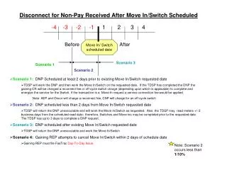
Fast fading. Doppler. dB. Path loss: 10n log10(d) +C; n=2-4. m. Channel Model for Train to Train Communication using the 400 MHz Band Cristina Rico García, Andreas Lehner, Thomas Strang and Korbinian Frank

E N D
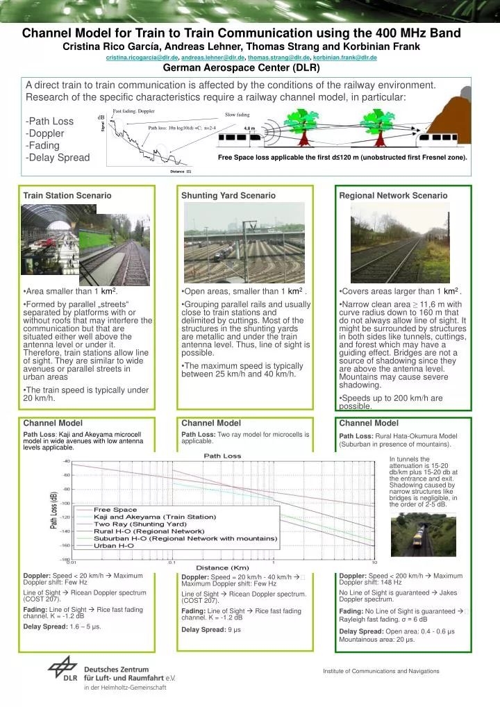
Fast fading. Doppler dB Path loss: 10n log10(d) +C; n=2-4 m Channel Model for Train to Train Communication using the 400 MHz Band Cristina Rico García, Andreas Lehner, Thomas Strang and Korbinian Frank cristina.ricogarcia@dlr.de, andreas.lehner@dlr.de, thomas.strang@dlr.de, korbinian.frank@dlr.de German Aerospace Center (DLR) A direct train to train communication is affected by the conditions of the railway environment. Research of the specific characteristics require a railway channel model, in particular:-Path Loss-Doppler-Fading-Delay Spread Slow fading Signal 4,8 m Free Space loss applicable the first d≤120 m (unobstructed first Fresnel zone). • Train Station Scenario • Area smaller than 1 km2. • Formed by parallel „streets“ separated by platforms with or without roofs that may interfere the communication but that are situated either well above the antenna level or under it. Therefore, train stations allow line of sight. They are similar to wide avenues or parallel streets in urban areas • The train speed is typically under 20 km/h. Distance • Shunting Yard Scenario • Open areas, smaller than 1 km2 . • Grouping parallel rails and usually close to train stations and delimited by cuttings. Most of the structures in the shunting yards are metallic and under the train antenna level. Thus, line of sight is possible. • The maximum speed is typically between 25 km/h and 40 km/h. • Regional Network Scenario • Covers areas larger than 1 km2 . • Narrow clean area ≥ 11,6 m with curve radius down to 160 m that do not always allow line of sight. It might be surrounded by structures in both sides like tunnels, cuttings, and forest which may have a guiding effect. Bridges are not a source of shadowing since they are above the antenna level. Mountains may cause severe shadowing. • Speeds up to 200 km/h are possible. • Channel Model • Path Loss: Kaji and Akeyama microcell model in wide avenues with low antenna levels applicable. • Doppler: Speed < 20 km/h Maximum Doppler shift: Few Hz • Line of Sight Ricean Doppler spectrum (COST 207). • Fading: Line of Sight Rice fast fading channel. K = -1.2 dB • Delay Spread: 1.6 – 5 μs. • Channel Model • Path Loss: Two ray model for microcells is applicable. • Doppler: Speed = 20 km/h - 40 km/h Maximum Doppler shift: Few Hz • Line of Sight Ricean Doppler spectrum. (COST 207). • Fading: Line of Sight Rice fast fading channel. K = -1.2 dB • Delay Spread: 9 μs • Channel Model • Path Loss: Rural Hata-Okumura Model (Suburban in presence of mountains). • Doppler: Speed < 200 km/h Maximum Doppler shift: 148 Hz • No Line of Sight is guaranteed Jakes Doppler spectrum. • Fading: No Line of Sight is guaranteed Rayleigh fast fading. σ = 6 dB • Delay Spread: Open area: 0.4 - 0.6 μs Mountainous area: 20 μs. In tunnels the attenuation is 15-20 db/km plus 15-20 db at the entrance and exit. Shadowing caused by narrow structures like bridges is negligible, in the order of 2-5 dB. Institute of Communications and Navigations