Download
1 / 15
160 likes | 476 Vues
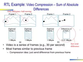
Only difference: ball moving. Frame 1. Frame 2. Frame 1. Frame 2. Digitized. Digitized. Digitized. Difference of. frame 1. frame 2. frame 1. 2 from 1. 1 Mbyte. 1 Mbyte. 1 Mbyte. 0.01 Mbyte. (. a. ). (. b. ). Just send difference.

E N D
Only difference: ball moving Frame 1 Frame 2 Frame 1 Frame 2 Digitized Digitized Digitized Difference of frame 1 frame 2 frame 1 2 from 1 1 Mbyte 1 Mbyte 1 Mbyte 0.01 Mbyte ( a ) ( b ) Just send difference RTL Example: Video Compression – Sum of Absolute Differences • Video is a series of frames (e.g., 30 per second) • Most frames similar to previous frame • Compression idea: just send difference from previous frame a
RTL Example: Video Compression – Sum of Absolute Differences compare • Need to quickly determine whether two frames are similar enough to just send difference for second frame • Compare corresponding 16x16 “blocks” • Treat 16x16 block as 256-byte array • Compute the absolute value of the difference of each array item • Sum those differences – if above a threshold, send complete frame for second frame; if below, can use difference method (using another technique, not described) Assume each pixel is represented as 1 byte (actually, a color picture might have 3 bytes per pixel, for intensity of red, green, and blue components of pixel) Frame 1 Frame 2
RTL Example: Video Compression – Sum of Absolute Differences • Want fast sum-of-absolute-differences (SAD) component • When go=1, sums the differences of element pairs in arrays A and B, outputs that sum SAD 256-byte array A integer sad B 256-byte array go
SAD A !go S0 sad B go go sum = 0 S1 i = 0 (i<256)’ S2 i<256 sum=sum+abs(A[i]-B[i]) S3 i=i+1 sad_ r eg = sum S4 RTL Example: Video Compression – Sum of Absolute Differences • S0: wait for go • S1: initialize sum and index • S2: check if done (i>=256) • S3: add difference to sum, increment index • S4: done, write to output sad_reg Inputs: A, B (256 byte memory); go (bit) Outputs: sad (32 bits) Local registers: sum, sad_reg (32 bits); i (9 bits) a
RTL Example: Video Compression – Sum of Absolute Differences • Step 2: Create datapath AB_addr A_data B_data Inputs: A, B (256 byte memory); go (bit) Outputs: sad (32 bits) Local registers: sum, sad_reg (32 bits); i (9 bits) i_lt_256 <256 8 8 9 i_inc !go S0 – i go i_clr sum = 0 8 S1 i = 0 sum_ld 32 (i<256)’ abs sum S2 sum_clr 8 i<256 32 32 sum=sum+abs(A[i]-B[i]) sad_reg_ld S3 i=i+1 + sad_reg sad_ reg=sum S4 32 Datapath sad
sum_clr=1 i_clr=1 i_lt_256 sum_ld=1; AB_rd=1 i_inc=1 sad_reg_ld=1 RTL Example: Video Compression – Sum of Absolute Differences • Step 3: Connect to controller • Step 4: Replace high-level state machine by FSM AB_addr A_data B_data go AB_ r d i_lt_256 <256 8 8 go’ S0 9 i_inc go – i sum=0 S1 i_clr i=0 8 sum_ld S2 32 abs sum i<256 sum_clr sum=sum+abs(A[i]-B[i]) S3 8 32 32 i=i+1 sad_reg_ld + S4 sad_reg=sum sad_reg a 32 Controller sad
RTL Example: Video Compression – Sum of Absolute Differences • Comparing software and custom circuit SAD • Circuit: Two states (S2 & S3) for each i, 256 i’s 512 clock cycles • Software: Loop (for i = 1 to 256), but for each i, must move memory to local registers, subtract, compute absolute value, add to sum, increment i – say about 6 cycles per array item 256*6 = 1536 cycles • Circuit is about 3 times (300%) faster (i<256)’ S2 i<256 sum=sum+abs(A[i]-B[i]) S3 i=i+1
Control vs. Data Dominated RTL Design • Designs often categorized as control-dominated or data-dominated • Control-dominated design – Controller contains most of the complexity • Data-dominated design – Datapath contains most of the complexity • General, descriptive terms – no hard rule that separates the two types of designs • Laser-based distance measurer – control dominated • SAD circuit – mix of control and data • Now let’s do a data dominated design
Data Dominated RTL Design Example: FIR Filter • Filter concept • Suppose X is data from a temperature sensor, and particular input sequence is 180, 180, 181, 240, 180, 181 (one per clock cycle) • That 240 is probably wrong! • Could be electrical noise • Filter should remove such noise in its output Y • Simple filter: Output average of last N values • Small N: less filtering • Large N: more filtering, but less sharp output Y X 12 12 digital filter clk
Data Dominated RTL Design Example: FIR Filter • FIR filter • “Finite Impulse Response” • Simply a configurable weighted sum of past input values • y(t) = c0*x(t) + c1*x(t-1) + c2*x(t-2) • Above known as “3 tap” • Tens of taps more common • Very general filter – User sets the constants (c0, c1, c2) to define specific filter • RTL design • Step 1: Create high-level state machine • But there really is none! Data dominated indeed. • Go straight to step 2 Y X 12 12 digital filter clk y(t) = c0*x(t) + c1*x(t-1) + c2*x(t-2)
Y X 12 12 digital filter clk 180 240 180 181 181 Data Dominated RTL Design Example: FIR Filter • Step 2: Create datapath • Begin by creating chain of xt registers to hold past values of X y(t) = c0*x(t) + c1*x(t-1) + c2*x(t-2) Suppose sequence is: 180, 181, 240 180 a
Y X 12 12 digital filter clk c0 c1 c2 * * * Data Dominated RTL Design Example: FIR Filter • Step 2: Create datapath (cont.) • Instantiate registers for c0, c1, c2 • Instantiate multipliers to compute c*x values y(t) = c0*x(t) + c1*x(t-1) + c2*x(t-2) 3-tap FIR filter x(t) x( t -1) x( t -2) x t0 x t1 x t2 X a clk Y
Y X 12 12 digital filter clk + + Data Dominated RTL Design Example: FIR Filter • Step 2: Create datapath (cont.) • Instantiate adders y(t) = c0*x(t) + c1*x(t-1) + c2*x(t-2) 3-tap FIR filter x(t) x( t -1) x( t -2) c0 c1 c2 x t0 x t1 x t2 X clk a * * * Y
Y X 12 12 digital filter clk Data Dominated RTL Design Example: FIR Filter • Step 2: Create datapath (cont.) • Add circuitry to allow loading of particular c register y(t) = c0*x(t) + c1*x(t-1) + c2*x(t-2) CL 3-tap FIR filter e 3 Ca1 2x4 2 1 Ca0 0 C x(t) x(t-1) x(t-2) c0 c1 c2 xt0 xt1 xt2 a X clk * * * yreg + + Y
Data Dominated RTL Design Example: FIR Filter y(t) = c0*x(t) + c1*x(t-1) + c2*x(t-2) • Step 3 & 4: Connect to controller, Create FSM • No controller needed • Extreme data-dominated example • (Example of an extreme control-dominated design – an FSM, with no datapath) • Comparing the FIR circuit to a software implementation • Circuit • Assume adder has 2-gate delay, multiplier has 20-gate delay • Longest past goes through one multiplier and two adders • 20 + 2 + 2 = 24-gate delay • 100-tap filter, following design on previous slide, would have about a 34-gate delay: 1 multiplier and 7 adders on longest path • Software • 100-tap filter: 100 multiplications, 100 additions. Say 2 instructions per multiplication, 2 per addition. Say 10-gate delay per instruction. • (100*2 + 100*2)*10 = 4000 gate delays • Circuit is more than 100 times faster (10,000% faster).