Download
1 / 21
220 likes | 380 Vues
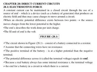
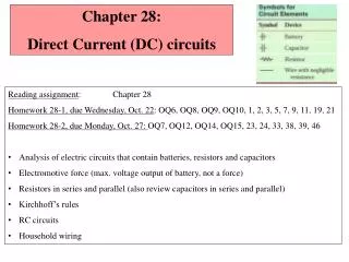
Chapter 26 Direct-Current Circuits. Study resistors in series and parallel Consider Kirchoff’s Rules The design and use of electronic measuring instruments R-C circuits The applications of circuits in household wiring. Resistors in Series and Parallel. Resistors in Series. Figure 26-1.

E N D
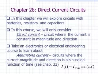
Chapter 26 Direct-Current Circuits • Study resistors in series and parallel • Consider Kirchoff’s Rules • The design and use of electronic measuring instruments • R-C circuits • The applications of circuits in household wiring
Resistors in Series and Parallel Resistors in Series Figure 26-1 Resistors in Parallel Figure 26-1 Chapter 26
Series and parallel combination resistors • Consider Problem-Solving Strategy 26.1. • Follow Example 26.1 guided by Figure 26.3 below. • Follow Example 26.2.
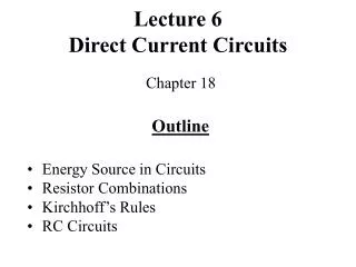
Kirchoff’s Rules I—junctions • The algebraic sum of the currents into any junction is zero.
Kirchhoff’s Laws Kirchhoff’s Current Law Proof Charge can’t build up at the junction. Figure 26-7 Kirchhoff’s Current Law - Example Figure 26-8 Chapter 26
Kirchoff’s Rules II—loops • The algebraic sum of the potential differences in any loop, including those associated with emfs and those of resistive elements, must equal zero.
Kirchhoff’s Voltage Law – Two Loop Example Figure 26-8 Loop 1 Loop 1 Loop 2 Loop 2
Kirchhoff’s Laws - A Single Loop Circuit Example 26-3 a) Solve for I b) Solve for Vab c) Solve for power output of the emf of each battery Figure 26-10 Chapter 26
Kirchoff’s Rules III—examples and strategy • Read through Problem-Solving Strategy 26.2. Figure 26.9 illustrates this strategy. • Refer to Example 26.3, illustrated by Figure 26.10.
Kirchoff’s Rules IV—examples • Refer to Example 26.4, illustrated by Figure 26.11. • Consider Example 26.5. • Refer to Example 26.6, illustrated by Figure 26.12. • Review Example 26.7.
R-C Circuits (Chapter 26, Sec 4) Charging a Capacitor 0.37 I0 0.63 Qf Time Constant Figure 26-20 Figure 26-21 (26-14) Chapter 26
R-C Circuits (Chapter 26, Sec 4) Discharging a Capacitor Time Constant (26-14) Figure 26-23 Figure 26-22 Chapter 26
D’Arsonval’s galvanometer • We’ll call it simply “meter” henceforth. • The meter is a coil of wire mounted next to a permanent magnet. Any current passing through the coil will induce magnetism in the coil. The interaction of the new electromagnetism and the permanent magnet will move the meter indicator mounted to the coil.
The Ammeter and Voltmeter • The ammeter (sometimes prefixed with milli or micro because the currents to be measured are routinely thousandths or millionths of an ampere) may be used to measure current OR voltage. A shunt resistor makes this conversion as shown below in Figure 26.15. • Consider Example 26.8 to follow a current example. Consider Example 26.9 to follow a voltage example.
Ohmmeters and digital multimeters • An ohmmeter is designed specifically to measure resistance. • Refer to Figure 26.17 and Figure 26.18 below to see an ohmmeter wiring diagram and a photograph of a digital multimeter. The multimeter can measure current, voltage, or resistance over a wide range.
Power Distribution Systems 240-V line black, red Neutral Black White 120 v One phase of the 240-V line We buy energy from the Power Company, not power kW x time = watt-seconds = Joules 1 kWh = (1000W) (3600 s ) = 3.6 x 10⁶ W-s = 3.6 x 10⁶ J
Fuses, circuit breakers, and GFI • A fuse will melt and a breaker will open the circuit if maximum current is reached. See Figure 26.26. • GFI stops further current flow when a sudden drop in resistance indicates that someone has offered a new path to ground. I don’t know if it will save this worker we see in Figure 26.27 who didn’t use a grounded drill.
The wiring diagram for a typical kitchen • Consider Figure 26.28 below. • Follow Example 26.14.
Average Retail Price of Electricity cents per kilowatt-hour