Download
1 / 56
570 likes | 690 Vues
Broad-band and Scalable Circuit-level Models of MSM PD for Co-design with Preamplifier in Front-end Rx Applications. Ph.D. Defense Spring, 2004 Cheol-ung Cha Advisor: Prof. Martin A. Brooke School of Electrical and Computer Engineering Georgia Institute of Technology Atlanta, GA, 30332.

E N D
Broad-band and Scalable Circuit-level Models of MSM PD for Co-design with Preamplifier in Front-end Rx Applications Ph.D. Defense Spring, 2004 Cheol-ung Cha Advisor: Prof. Martin A. Brooke School of Electrical and Computer Engineering Georgia Institute of Technology Atlanta, GA, 30332
Outline • Optical Interconnects and Communications • MSM Photodetector • Preamplifier • Modeling Methodology • Motivation • Previous Modeling Work • Partial Element Equivalent Circuit (PEEC) Model • Proposed Modeling Method • Partial Elements (PEs) and Test structures • Measurement-based PEEC (M-PEEC) Model • Modeling Procedure • Case study: Straight Line Modeling • Calibration • On-wafer Calibration • MSM Photodetector Modeling • Partial Elements (PEs) and Test structures • M-PEEC Model Extraction • Optimization Results • Conclusions
Electrical Signal Re-timer Laser Driver MUX Power Control PLL Serializer Tx Recovered Signal Decision Circuitry TIA DEMUX Limiting Amp. AGC Clock Recovery Deserializer Rx • General OIC system Optical Interconnects & Communications Transmission channel
Lightwave Interdigitated fingers - + - B E E E Contact pads A Frame MSM PD: What is MSM PD? • Metal-Semiconductor-Metal Photo-Diode (MSM PD) • Role : Optical signal Electrical signal • Condition : hv >Eg (optical) and reverse voltage bias (electrical)
MSM PD: Advantages • Advantages of MSM PD • Low capacitance • Broad bandwidth • Ease of monolithic integration with FETs • Ease of alignment • Low dark current (~ nA scale) • Drawback of MSM PD • Low responsivity (about 0.2~0.4) (Low output current level requires sensitive preamplifier design) • FWHM : 12.46ps
MSM PD: Capacitance • Capacitance is • Major parasitic component of the MSM PD • Main limitation factor for high-frequency (multi-GHz) applications • Three times smaller than that of PIN PD (Large detection area enables higher alignment tolerance for packaging) • Conventional formulas are based on the Microwave theory • Obtained without illumination of light • Obtained without considering frame Ex) Conformal mapping theory only considered interdigitated fingers without considering the effects of frame and light illumination.
100 fF 3dB 80 fF 50 fF 2.2 4.2 3 • Simulation results with preamplifier with respect to different capacitance values : 50, 80, 100 fF MSM PD: Capacitance
MSM PD: Capacitance Pad Frame MSM PD w/ & w/o illumination of light
MSM PD: Capacitance • Comparison of measured S22
MSM PD: Capacitance • Interdigitated fingers: Conformal mapping theory Depends on size, finger width, and spacing where , , • Frames: Complete elliptic integral of the second kind , Where , and
MSM PD: Capacitance • Light illumination: External quantum efficiency where and • Total capacitance
MSM PD: Capacitance • 20/1/2 MSM photodetector Theory Measurement By conformal mapping 10 fF NA Capacitance of interdigitated electrodes (Cfingers) By proposed formula 5.5 fF 6 fF Capacitance of Frames (Cframe) What makes this huge difference? By proposed formula 2.7 fF By subtraction 3 fF Capacitance from illumination of light (Clight) 18.2 fF 18 fF Superposition (CTotal)
where is the saturated carrier velocity and d is the distance of travel. • Transit time • The time for a carrier to take to travel through the active region and collected by contacts. • Low mobility of hole causes a long tail in the impulse response and small bandwidth in the frequency response. • The transit time is MSM PD: Transit time & BW Depends on finger spacing • Bandwidth (BW) • Two main factors that limit the speed is “capacitance” and “transit time” • Trade off between capacitance and transit time (size, finger spacing, and width). • The BW is RC time const. Transit time const.
3dB freq. of transit time const. 3dB freq. of RC time const. 3dB freq. of total time const. • Bandwidth of Square MSM PDs MSM PD: Bandwidth
20x20 MSM PDs 40x40 MSM PDs 60x60 MSM PDs 80x80 MSM PDs • Total bandwidth of MSM PDs (Trade off between RC and transit time const.) MSM PD: Bandwidth
10 Gbps 20 Gbps 30 Gbps • Equivalent-circuit model of pad and MSM PD MSM PD: Lumped Equivalent-circuit Model
where the open-loop gain. xs xo + Ao(ω) - xf β • Key performance metrics of optical receiver • Bandwidth, Sensitivity, Noise, and Gain • Mainly determined by front-end (preamplifier and photodetector) • TransImpedance Amplifier (TIA) • Convert low-level photocurrent to usable voltage signal • Feedback in preamplifier • Extending BW • Reducing noise (Good sensitivity) • Controlling input and output impedance • The close-loop gain is Preamplifier: Performance Metrics
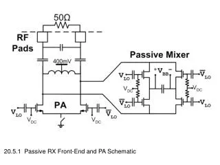
BERT Modulator Laser 1.2 Gbps Oscilloscope 2.5 Gbps TIA MSM PD 2 Gbps 50 Ohm Matched 3Gbps 6Gbps • MSM PD with commercial TIA ( Maxim 2.5 Gbps TIA) Preamplifier: Eye Diagrams The output current of MSM PD (60/1/2) is too weak to be detected by oscilloscope
Outline • Optical Interconnects and Communications • MSM PD • Preamplifier • Modeling Methodology • Motivation • Previous Modeling Work • Partial Element Equivalent Circuit (PEEC) Model • Proposed Modeling Method • Partial Elements (PEs) and Test structures • Measurement-based PEEC (M-PEEC) Model • Modeling Procedure • Case study: Straight Line Modeling • Calibration • On-wafer Calibration • MSM Photodetector Modeling • Partial Elements (PEs) and Test structures • M-PEEC Model Extraction • Optimization Results • Conclusions
, Solution Co-design of photodetector with preamplifier is a solution : when a circuit designer design circuitry, he/she can choose proper device specifications such as device size, finger spacing and width, and thickness of active layer to satisfy the requirements. • Demand for higher bandwidth and speed requires well-designed front-end (preamplifier with photodetector) of optical Rx. • Front-end is a dominant component in a Rx because the sensitivity of the Rx is mainly determined by the noise factor of the front-end. Motivation: Higher Performance • Reductionin bandwidth comes from the parasiticcapacitance of a photodetector and pad. • The capacitance of bond-pad is typically 10–50 fF(significant for GHzcircuitry). -Flip-chip bonding techniques can be used to reduce parasitics at the interface between InGaAs and CMOS. • The capacitance of commercial PIN and avalanche photodiode is 200–900 fF. - Using MSM PDs, this value can be reduced up to 50-300 fF. (The reduced capacitance would allow enough budgets for circuit design)
Motivation: Modeling Method • Modeling methodology for co-design should be • Easy to use (Needs to be integrated into existing circuit design environment such as HSPICE and ADS. - This approach circumvents theinconvenient, iterative interface between a photonic device simulatorand a circuit design tool. • Fast - The finite-element methodsneed long simulation time and huge memory resource • Accurate - Existing analytical equation-based methods are not accurate. • Scalable - Modeling method can predict the model of different dimensional device.
Numerical (EM full wave-based) Analytical (Equation-based) Empirical (Measurement-based) Modeling Methodology Tree Frequency domain Time domain Measurement-based Partial Element Equivalent Circuit (M-PEEC) Improved in this research for the capacitance modeling of the MSM PD Differential equation (Grids on whole area) Integral equation (Grids only on conductors) Proposed in this research Finite Methods (Discretization) Method of Moments (MoM) Electric Field Integral Equation Finite Difference Time Domain Finite Element (Spatial discretization) Partial Element Equivalent Circuit (Discrete Approx. of EFIE) Finite Element Equivalent Circuit
Previous Modeling Work • Earlier work in high frequency component modeling mainly originated from the microwave engineering community. • Three fundamental methodologies • Analytical equation-based modeling method • Direct derivation from first physical principles - very few, available only for very simple structures • Generally difficult and time consuming to develop • Not very flexible • Not accurate • Numerical EM-full wave based modeling method • Accurate • Highly flexible • Very slow and requiring huge memory resource, so it’s not practical for complex geometry system analysis
Previous Modeling Work • Two dominant methods exist (continued) - The Finite Element Method (FEM) • FEM yields high accuracy for 3 dimensional structures. • Grids structure into many small pieces, and solves Maxwell’s Equations • - The Method of Moment (MoM) • MoM is a 2 1/2-D method with less accuracy in 3 dimensions. • Assumes a conductor height of zero. • Grids structure into many small pieces, and solves Green’s Function • Measurement-based modeling method • Measured data from time or frequency domain can be fit to a circuit model using optimization techniques • Non-ideal processing effects can be considered • The method allows for statistical modeling • Very accurate for measured structures • Not very flexible Improved measurement-based, scalable, and flexible modeling method
Three dimensional partial element equivalent circuit (PEEC) model was originated from high-speed interconnect modeling in 1970s[Ruehli]. • The PEEC method is based on Maxwell’s integral equation that is interpreted in terms of RLC elements and their couplings. • Maxwell’s Electric Field Integral Equation (EFIE) • The advantages of the PEEC method are • The output of the PEEC analysis is spice-like equivalent-circuit model (it can be easily integrated with other circuit models such as transistor models into a conventional circuit simulation tools such as SPICE). • The PEEC models work equally well in the time and frequency domains. • The PEEC analysis can reduce simulation time by using Maxwell’s integral equation. • The PEEC models include cross coupling terms. Partial Element Equivalent Circuit (PEEC) Model
Square Partial Element (PE) Pad Partial Element (PE) CS15 CP15 CS13 CS35 CP13 CP35 LS22 RS22 RS44 LS44 LP22 RP22 RP44 LP44 CS11 CS33 CS55 CP11 CP33 CP55 LS24 LP24 Partial Element Equivalent Circuit (PEEC) Model
C15 Capacitive cell_1 Capacitive cell_3 Capacitive cell_5 C13 C35 L22 R22 R44 L44 w C15 C15 C15 d Inductive cell_2 Inductive cell_4 L24 where and are the index of the capacitive cells connected to inductive cell i. • Primitive PEEC cell Partial Element Equivalent Circuit (PEEC) Model • In the general case, the ith circuit equations of n inductive and m capacitive cells are
Outline • Optical Interconnects and Communications • MSM PD • Preamplifier • Modeling Methodology • Motivation • Previous Modeling Work • Partial Element Equivalent Circuit (PEEC) Model • Proposed Modeling Method • Partial Elements (PEs) and Test structures • Measurement-based PEEC (M-PEEC) Model • Modeling Procedure • Case study: Straight Line Modeling • Calibration • On-wafer Calibration • MSM Photodetector Modeling • Partial Elements (PEs) and Test structures • M-PEEC Model Extraction • Optimization Results • Conclusions
Partial Elements (PEs) & Test Structures • If we can accuratelymodel individual parts of a structure, then we can predictively model any structure comprised of those parts accurately. • Those individual parts are called “Partial Elements” (PEs). • “Test structures” are designed, fabricated, and measured to extract the equivalent circuit models, which are called “ Measurement-based partial element equivalent circuits (M-PEECs).” • Partial elements must have enough sensitivity within a test structure in order to be deembedded. • Initial guesses are derived from measured S-parameters. • Optimized M-PEEC models, which are resulted from one test structure, are used in extracting other M-PEEC models for subsequent test structures. • Models of different geometry structures can be created by combining M-PEEC models of partial elements.
Measurement-based PEEC (M-PEEC) Model • The M-PEEC models have these advantages: • The M-PEEC models are accurate because they are derived from test structures and measurements that automatically include unexpected processing effects such as processing fluctuations, uneven depositions, and non-ideal material properties. • The M-PEEC models can be generated easily and simulated very quickly in a standard and conventional circuit simulator. • The M-PEEC models can be applicable to both electrical and optical devices (passive and active devices) and interconnects modeling which are electrically long and short structures. (In case of optical devices modeling, iterative and inconvenient interface between optical device and electrical circuit simulators can be overcome). • The M-PEEC models are independent of technology or the process in which the structures are fabricated because changed and modified factors are automatically taken into account in the measurements. • The M-PEEC models are scalable and predictive since equivalent-circuit models of different dimensional devices can be constructed from obtained several M-PEEC models. • The M-PEEC models can take into account statistical information in the models.
What structure to be considered? Generate Design Rule Library Design Desired Device Define Partial Elements (PEs) Design Rule Checking Design & Fab. Test Structures Fail Pass Co-simulation with Circuitry in SPICE-type Simulator Calibration & Measurement Extract M-PEEC modelsusing optimization Accurate simulation results Modeling Procedure • Design and Modeling Flow
Straight line is meshed into 20 square PEs and pads by commercial EM simulator (MoM in ADS) Case Study: Straight Line Modeling 20 square PEs Coplanar waveguide
Square Partial Element (PE) Pad Partial Element (PE) Square M-PEEC Pad M-PEEC • Straight line is meshed into 20 square PEs and 2 pads by the proposed modeling method. Case Study: Straight Line Modeling
Square Partial Element (PE) Pad Partial Element (PE) • Two PEs and their parameter values of M-PEECs Case Study: Straight Line Modeling
Mom model Measured data M-PEEC model Case Study: Straight Line Modeling • S11 comparison: measured data, MoM model, and M-PEEC model.
Mom model Measured data M-PEEC model Case Study: Straight Line Modeling • S21 comparison: measured data, MoM model, and M-PEEC model.
Outline • Optical Interconnects and Communications • MSM PD • Preamplifier • Modeling Methodology • Motivation • Previous Modeling Work • Partial Element Equivalent Circuit (PEEC) Model • Proposed Modeling Method • Partial Elements (PEs) and Test structures • Measurement-based PEEC (M-PEEC) Model • Modeling Procedure • Case study: Straight Line Modeling • Calibration • On-wafer Calibration • MSM Photodetector Modeling • Partial Elements (PEs) and Test structures • M-PEEC Model Extraction • Optimization Results • Conclusions
Reference plane On-wafer Calibration • Calibration : Defining the ends of a measurement system and the begins of a DUT
Original Load Open Short Trimmed Load On-wafer Calibration • SOL on-wafer calibration • SOL (Short-Open-Load) • On-wafer : Calibration structures are on the same substrate with DUT NiCr Resistors
28.809 Ohm 29.286 Ohm On-wafer Calibration • Un-trimmed load • Designed for 25 Ohm. • NiCr is used. 49.873 Ohm 50.025 Ohm • Laser-trimmed load • Optimized for 50 Ohm. • NiCr is used.
Outline • Optical Interconnects and Communications • MSM PD • Preamplifier • Modeling Methodology • Motivation • Previous Modeling Work • Partial Element Equivalent Circuit (PEEC) Model • Proposed Modeling Method • Partial Elements (PEs) and Test structures • Measurement-based PEEC (M-PEEC) Model • Modeling Procedure • Case study: Straight Line Modeling • Calibration • On-wafer Calibration • MSM Photodetector Modeling • Partial Elements (PEs) and Test structures • M-PEEC Model Extraction • Optimization Results • Conclusions
Interdigitated PE Pad PE Line PE Test structures • Partial Elements (PEs) and Test structures for MSM PD modeling Partial Elements (PEs) and Test structures
Coupling Inductance Coupling Capacitance Interdigitated partial element (PE) Partial Elements (PEs) and Test structures • “MSM PD” is comprised of “interdigitated partial elements” and couplings
Pad Extracting Circuit model This obtained “Pad M-PEEC” is used for “Line M-PEEC” extraction. “Line M-PEEC” modeling Step I: Pad M-PEEC Model Extraction
Line Pad Line Line Line Line This obtained “Line M-PEEC” is used for “Interdigitated M-PEEC” extraction. Step II: Line M-PEEC Model Extraction
Line M-PEEC Interdigitated M-PEEC Line M-PEEC Pad This obtained “Interdigitated M-PEEC” is used for “MSM PDs” modeling. Step III: Interdigitated M-PEEC Model Extraction
Pad Partial Element (PE) Line Partial Element (PE) Interdigitated Partial Element (PE) • Three PEs and their parameter values of M-PEECs M-PEEC Model Extraction : Parameters
Pad PE Line PE Interdigitated PE Coupling Inductance Coupling Capacitance Optimization Results: Scalable Model
40/1/1 um MSM Photodetector Optimization Results : Scalable Model