Download
1 / 21
220 likes | 312 Vues
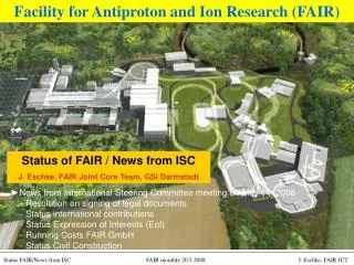
High Intensity Challenges of the FAIR Project Oliver Boine-Frankenheim, GSI, Darmstadt. Nov. 7, 2007: FAIR project start event. German Minister Ms. Schavan on November 7, 2007. Partners signing communiqué: Austria, Germany, Spain, Finland, France, Poland,

E N D
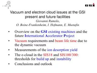
High Intensity Challenges of the FAIR ProjectOliver Boine-Frankenheim, GSI, Darmstadt
Nov. 7, 2007: FAIR project start event German Minister Ms. Schavan on November 7, 2007 Partners signing communiqué: Austria, Germany, Spain, Finland, France, Poland, Romania, Russia, Sweden, Great Britain
FAIR start event • 1400 international participants • 500 international scientists attended the symposium on the Physics of FAIR
FAIR rings and parameterbaseline layout This presentation: SIS-18 and SIS-100 L=1080 m 100 m SIS-100/300 p-linac L=216 m SIS-18 UNILAC Radioactive Ion Production Target Existing facility UNILAC/SIS-18: provides ion-beam source and injector for FAIR HESR Super FRS Accelerator Components & Key Characteristics Ring/Device Beam Energy Intensity SIS100 (100Tm) protons 30 GeV 4x10¹³ 238U28+ 1 GeV/u 5x10¹¹ (intensity factor 100 over present, short single bunch) SIS300 (300Tm) 238U92+ 34 GeV/u 2x10¹⁰ CR/RESR/NESR ion and antiproton storage rings HESR antiprotons 14 GeV ~1011 Super-FRS rare isotope beams 1 GeV/u <109 Anti-Proton Production Target CR FLAIR RESR NESR New future facility: provides ion and anti-matter beams of highest intensities and up to high energies
Required FAIR beam intensitiesHeavy ions SIS 100 cycle 5x10¹¹ U28+ SIS 18 *UNILAC studies: L. Gröning’s talk, Tuesday • FAIR specific beam dynamics challenges: • Intensities at the ‘space charge limit’ • High beam quality (weak or lost Landau damping) • Long accumulation time (1 s) in SIS-100 • Reducing beam loss induced pressure increase
SIS-18 intensitiesstatus and upgrade parameters (long. space charge effect on the UNILAC micro-bunches) Injection energy: 11.4 MeV/u (acceptance) Incoherent space charge tune shift: SIS-18 L=216 m ≈ 5x10⁹ U28+ ≈ 3x10⁹ U73+ Challenge: Working point optimization and resonance compensation for low beam loss (< 10 %). G. Franchetti’s talk on Tuesday
U28+ lifetime in SIS-18low beam intensities Loss of one or more electrons: G. Weber, Heidelberg, 2006 (Lifetime)-1: Born approximation: G. Weber 2004 Born 2001 CTMC simulations: R. Olson et al., J. Phys. B (2004) lifetime [s] CTMC Energy [MeV/u]
SIS-18 upgradeControl of the dynamic vacuum pressure Dynamic pressure: Beam loss mechanisms: U28+ -> U29+ (stripping) U73+ -> U72+ (capture) Desorption coefficient: U28+ lifetime in SIS-18 (C. Omet) 1.8E10 60 % loss Combined pumping/collimation ports behind every dipole group. NEG coated vacuum chambers 8E9 N(t) 270 ms • Challenges: • - increase pumping speed • - localize beam loss • minimize desorption P.Spiller
SIS-18 upgradenew dual rf system Bucket filling factor U28+: 2/3 Bf=0.35 ! φs=450 Additional compact rf cavity system: + increase rf bucket area + flattened bunch profiles For SIS-18 operation with 2.7 Hz the existing rf voltages are not sufficient. Magnetic Alloy (MA) filled rf cavity • Challenges: • Space charge induced voltage reduction: ≈40 % • Bunch stability with space charge • Control of bunch deformation due to beam loading (low Q) P. Hülsmann et al.
SIS-100 bunch compression Single bunch formation 0.2->1.5 GeV/u 8 bunches ‘bunch merging’ pre-compression rotation extraction ∆Qsc≈ -0.6 ! bunch compressor loaded with 20 MA cores rf compressor section (≈40 m) SIS 100 L=1080 m RF cavity systems in SIS 100: Final bunch parameters: Particles/bunch bunch length 1.5 GeV/u U28+ 5x10¹¹ 60 ns 29 GeV/u p 2-4x10¹³ 25 ns
SIS-100 bunch pre-compressionbarrier rf buckets with beam-loading and space charge Longitudinal space charge impedance: Stationary bunch profile from the Haissinski equation (no rf): with Vlasov simulation including cavity beam loading and space charge. space charge reduces the effect of beam loading Bunch area increases by 20 % during pre-compression. Longitudinal dilution budget in SIS-100: Factor 2.
SIS 100 dipole magnetsfull size model from Babcock Noell GmbH Superconducting magnet with 4 T/s and Bmax= 1.9 T Dipole magnet with elliptical beam pipe 1st Full Size Dipole is ready for testing! 2D/3D field calculations P. Spiller, SIS-100, Tuesday afternoon
SIS-100 field quality and beam lossat injection energy 0.2 GeV/u SIS-100 transverse apertures at injection (0.2 GeV/u) dynamic aperture beam lattice aperture magnet aperture Simulation scan of the SIS-100 dynamic aperture G. Franchetti (2008) tune space charge tune spread Long-term (up to 1 s) 3D particle tracking studies with ‘frozen’ space charge indicate a space charge limit at 3x10¹¹ U28+ (design 5x10¹¹). • High intensity challenges for SIS-100: • Long time scales up to 106 turns (1 s) • Space charge tune shift of ΔQsc=-0.25 • ‘Thick’ medium energy beams (2/3 filling factor) • Optimized working point for < 5 % loss. G. Franchetti, SIS-100 technical design report (2008)
Transverse impedances in SIS-18/100 Ferrite loaded kicker modules Doliwa, Weiland (2006) • Specific SIS-18/100 impedance issues: • - Low frequencies and beam energies • - Thin (0.3 mm ) stainless steel pipe (optional corrugated) • - Ferrite or magnetic alloy loaded ring components • Distributed collimation system SIS-18 transverse impedance spectrum (200 MeV/u) dc: Loss of Landau damping wall (smooth) ‘Space charge impedance’: • e-clouds ?: • electrons from residual gas ionization and beam loss. • e-accumulation: survival rate in bunch gaps ? • transv. ‘impedance’: Ohmi, Zimmermann, PRL (2000) • - long. impedance: Al-khateeb et al. NJP (2008) f0 kicker (y) kicker (x) e-cloud
Resistive (thin) beam pipe in SIS-100Transverse impedance and shielding Transmission coefficient ! In SIS-100 the thin (0.3 mm) beam pipe is the dominant transverse impedance contribution ! SIS 100 transverse resistive wall impedance (200 MeV/u) Transmission: Structures behind the pipe might contribute ! SIS-18: Measured growth rate of the resistive wall instability agrees with impedance formula. Al-khateeb, Hasse, Boine-F., Daqa, Hofmann, Phys. Rev. ST-AB (2007)
Transverse Impedance Budget with Space Charge coasting beam stability boundaries (from dispersion relation) • Specific issues for SIS-100: • Long time scales (up to 1 s) • Image current and space charge effects • Long bunches and ‘dc-like’ barrier rf beams • Potential cures: • octupoles and nonlinear space charge • (Kornilov et al. PRST-AB 2008) • feedback systems Chromatic damping Challenges: - Octupoles and dynamic aperture - 3D space charge and image current effects • Head-tail instability in SIS-100 (talk by V. Kornilov this Monday afternoon): • Sacherer’s formula predicts head-tail modes with 70 ms growth rate in SIS-100 ! • 3D simulation studies including: resistive wall impedance, image currents, space charge, nonlinear rf. • -’Mode coupling regime’: (νs: synchrotron tune)
Transverse Schottky signals with space chargeUnderstanding signals from stable beams with space charge coasting beam (measurement in SIS-18) bunched beam (simulation) coherent betatron frequencies: Modified Schottky band: Central line is not shifted, but synchrotron satellites are. Amplitudes seem to follow the dc results P(z). Q0 Q0+νs The measured Schottky band (upper sideband) with space charge is deformed, but not shifted. Transverse Schottky signals from real or from computer beams provide important information on the mode structure and Landau damping with space charge. Boine-Frankenheim, Kornilov, Paret, PRST-AB (2008)
Decoherence with image currents and space charge3D simulation studies with space charge and impedances Injected bunch in SIS-100 with a transverse offset. coherent tune shift: I(z) Bunch profile bunch Initial offset dc Beam pipe z 0 L=2πR Coherent and incoherent tune spread along the bunch: Interplay of space charge and image currents: -mode coupling (due to image currents) -persistent bunch modes -halo formation !
Summary A next design iteration of the FAIR synchrotron facilities has been finalized. (see latest Technical Reports.) For high intensity operation a number of optimization challenges have still to overcome. Of outmost importance is to further increase the beam intensity and quality in the UNILAC/SIS-18 injector. SIS-18/SIS-100 high intensity challenges: - Working point and resonance compensation for low beam loss. - Control of the dynamic vacuum pressure for heavy ions. - Complex RF manipulation at high beam intensities. - Control of coherent beam instabilities. FAIR related talks: V. Kornilov, Coherent instabilities in SIS-100, Monday afternoon G. Franchetti, Space charge resonances in SIS-18, Tuesday afternoon P. Spiller, SIS-100, Tuesday afternoon L. Gröning,Emittance grwoth stdy in the UNILAC, Tuesday morning
Observers: in 2016 Thank you ! Austria China Finland France Germany Greece India Italy Poland Slovenia Spain Sweden Romania Russia UK
SIS-18 working point and resonance compensation N7+ G. Franchetti’s talk on Tuesday Challenge: Multi-turn injection (MTI) and working point optimization for low beam loss (< 10 %).