Download
1 / 59
730 likes | 834 Vues
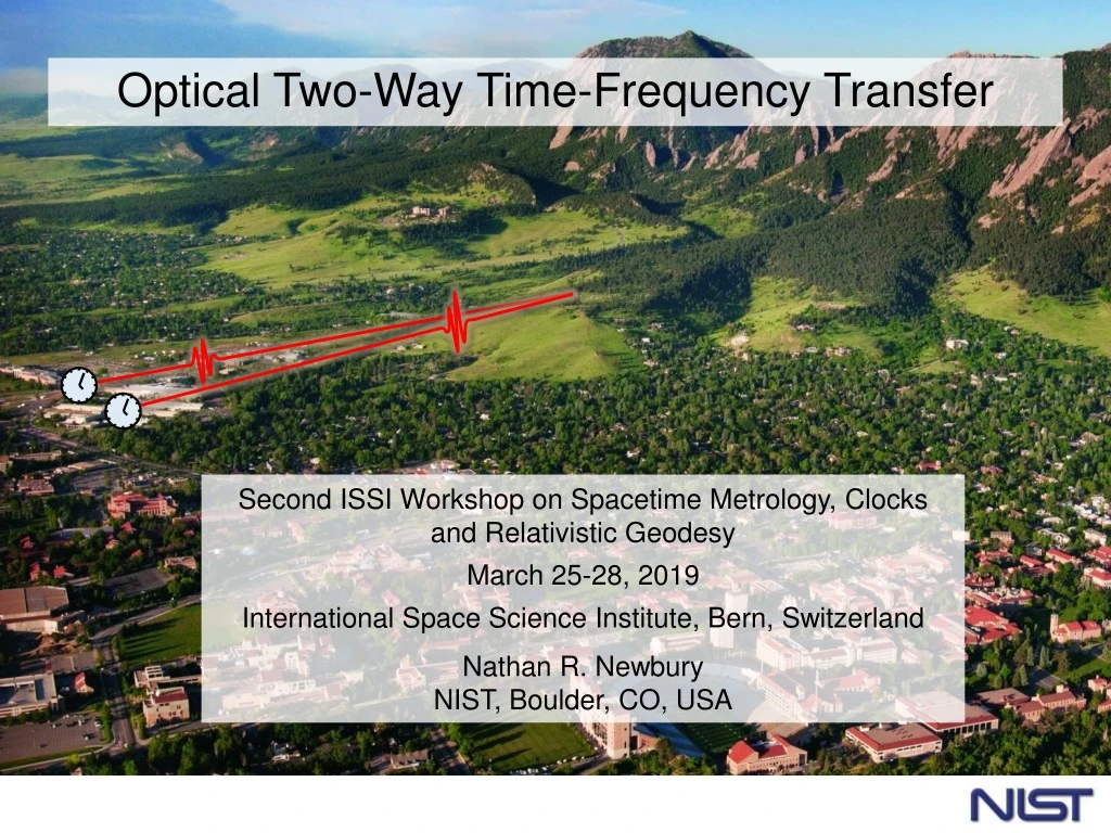
Optical Two-Way Time-Frequency Transfer. Second ISSI Workshop on Spacetime Metrology, Clocks and Relativistic Geodesy March 25-28, 2019 International Space Science Institute, Bern, Switzerland Nathan R. Newbury NIST, Boulder, CO, USA. Team.

E N D
Optical Two-Way Time-Frequency Transfer Second ISSI Workshop on Spacetime Metrology, Clocks and Relativistic Geodesy March 25-28, 2019 International Space Science Institute, Bern, Switzerland Nathan R. Newbury NIST, Boulder, CO, USA
Team Laura Sinclair, Jean-Daniel Deschenes*, Hugo Bergeron, William Swann, Isaac Khader, Martha Bodine, Esther Baumann, Fabrizio Giorgetta, Paritosh Manurkar, Sarah Stevenson, Jennifer Ellis, Emily Hannah, Nate Newbury *Octosig
Goal: enable future femtosecond clock network OpticalTWTFT OpticalTWTFT ~ ~ ~ Some uses: • Time/frequency dissemination • Distributed coherent sensing (active or passive) • Navigation (high precision & gps denial) • Secure communications …. Femtosecond Clock Network Remote site Master Optical Oscillator/Clock quartz oscillator or optical cavity
Outline • Introduction • Turbulence • Comb-Based OTWTFT: basic system and results • Overview of configurations and tests conducted • Conclusion
Our Clock Clock Reference plane Ticks @ 5 ns fs locked to underlying oscillator Self-referenced comb Cavity-stabilized laser Comb Atoms rarely Quartz/DRO 10 GHz oscillator Controller: Count and “label” pulses Define this pulse arrival at reference plane as 12:00:00.000000000000000
Free-space transfer: Turbulence, platform motion… Clock Clock Frequency Comb Frequency Comb • Amplitude noise & signal loss • From turbulence (scintillation & beam wander) • From obstructions & platform motion • Well-known from free-space optical communications • Phase noise (time-of-flight variations) • From turbulence (“piston effect”) • From platform motion 1st order Doppler shifts -> Need less than 3 nm/sec to reach v/c <
Atmospheric Turbulence: “textbook” Kolmogorov scaling density variations -> index of refraction variations -> random phase mask -> time of flight variations Spatial power spectrum of index fluctuations Input k< 1/L0 Outer Scale Inertial “Kolmogorov scaling” Inertial range Dissipative k < 1/l0 Inner Scale wavevector (k) From Andrews, Phillips, and Hopen “Laser Beam Scintillations with Applications”, SPIE Press (2001)
Temporal Power Spectral Density of Timing JitterTaylor’s Frozen Turbulence Hypothesis wind (vx ) Predicted Timing Jitter Outer scale L0= 10 m Cn2 = 1x10-14 m-2/3 vx = 1 m/s GT spectrum* Standard assumption (Van Karman) Kolmogorov scaling ~ f -8/3 input region inertial region ~vx/2pL0 *Greenwood and Tarazano, 1974
But the link is still reciprocal Clock Clock Frequency Comb Frequency Comb Turbulent Atmosphere is reciprocal* For two-waysingle-modelink, time-of-flight variations are common mode (not true for a multi-mode link) * J. Shapiro J. Opt. Soc. Am.61 492 (1971); J. Shapiro & A. Puryear, J. Opt. Commun. Netw. 4 947 (2012); R. R. Parenti et al., Opt. Exp.20 21635 (2012)
Two-Way Time Transfer: Basic Concept Site A Site B tA=0 tB=0 Timer Timer tB→A=Tlink-DtAB tA→B=Tlink+DtAB — DtAB Clock Time Offset Requires a “Reciprocal” Link A single-mode optical link is reciprocal!
Two-Way Time Transfer + Feedback Synchronization Site A Site B feedback Timer tA→B Timer tB→A Communication link — DtAB Real-time calculation
Two-Way Time Transfer: With Combs Site A Site B Timer Timer tB→A=Tlink-DtAB tA→B=Tlink+DtAB Comb timing is at femtosecond level! But timing information lost in photodetection …still picosecond level timing
Dual Comb Measurement Technique frep,A Comb 1 • Pulses from Comb A “downsample” pulse train from Comb B Digitizer Interferogram: • Cross-correlation • Downsampled pulse train Dfr Comb 2 frep,B Ampl. Time” Our system: TRed = 10 ns = 1/100 MHz dT = 300 fs dT/ TRed =30,000 (Downsampling factor)
Detection of Pulse Arrival with Femtosecond Precision Analogous to high-speed Sampling Oscilloscope Comb 1 Combs phase-locked to clock with differing repetition rate, Dfr = fr1 – fr2 Comb 2 dtclock Comb Comb 1/fr1 1/fr2 1/Dfr+ dtclock(fr/Dfr) 1/Dfr 1/Dfr Interferogram (cross-corr.) x x x x x x x x x x x x x x x x x x x x x x x x x x x x x x x x x x x x x x x x x x x x x x x x x x x x x x x x x x x x x x x x x x x x x x x x x x x x x x x x x x x x x x x x x x time Small timing shifts are “amplified” in the interferogram spacing by (fr/Dfr= 100,000)
Comb Pulse Arrival Detection “Linear Optical Sampling” approach Purposefully run clocks at different rates Site A Site B (fr+Dfr)-1 fr-1 Controller Controller Linear sampling of Comb A arrival by Comb B Linear sampling of Comb A arrival by Comb B — tA→B tB→A DtAB Clock Time Offset Time offset at 2kHz update with femtosecond precision but • 5 nanosec ambiguity (which comb pulse?) • Clocks tick at different rates…cannot “synchronize”
Comb-based Synchronization System Timing Exchange CW Laser Coherent TX/RX CW Laser Coherent TX/RX Coarse Two-way & Comms Coarse Two-way & Comms Controller Transfer Comb Remote Comb Controller Comb-based timing measurement Comb-based timing measurement Master Comb Synch.Equation Clock Output Clock Output 10-100 Hz Feedback BW Three signals between sites: • Phase modulated cw light for “coarse” two-way timing • Comb light for “fine” two-way timing • Coherent communication (to close the loop) Plus full calibration of each terminal delays for “absolute” time
Comb-based Synchronization System Timing Exchange Clock Output Clock Output Out-of-Loop Verification
Experimental Setup for 4 km Folded Link Across the NIST Campus ~5 mW launch Free-space terminals FPGA controllers Frequency comb transceivers
One-way (time-of-flight) vs. Two-way (clock timing) One-way (DTA) Time Variation (psec) Air Temperature (C) Two-way: TAB Two-way (TAB): x2000 expanded view Clock Timing (fs) Suppression of variations in path length to fsec level
Residual Frequency Uncertainty 90% Link availability Shorted-path Optical Clocks Also … No Systematic Bias at the 2.6x10⁻¹⁹ Level
O-TWTFT: Experiments Under Investigation Completed Carrier-Phase OTWTF for ultra-precise clock comparisons Limits to Future Ground-to-Satellite Links Applications to Coherent Sensing? Multi-Node network Sub-fs clock Synchronization with 25 m/s Motion O-TWTFT Comparison of Atomic Optical Clocks Simplified Picosecond Synchronization Coherent 10 GHz – Synched Microwave Osc. Synchronization Across 12 km of Air Modifications to support ultra-long distance links* * over 1-10 km-scale testbeds
O-TWTFT: Over strong turbulence Under Investigation Completed Ultra-precise clock comparisons ~ 1e-17 @ 1 sec Limits to Future Ground-to-Satellite Links Applications to Coherent Sensing* Multi-Node network Sub-fs clock Synchronization with 25 m/s Motion O-TWTFT Comparison of Atomic Optical Clocks Simplified Picosecond Synchronization Coherent 10 GHz – Synched Microwave Osc. Synchronization Across 12 km of Air Modifications to support ultra-long distance links** *At white paper level ** over 1-10 km-scale testbeds
Valmont Synchronization Across 12 km of Strong Turbulence Butte NIST Path: 12 km highly turbulent path over a City 5.8 km Collaborated with JH APL to verify compatible with Adaptive Optics Terminals Same results for “tip/tilt” terminals and Adaptive Optics terminals
Turbulence Causes many short Dropouts Dropout = period during which received power is below ~2.5 nW threshold 12 kilometer Strong turbulence Moderate turbulence • Most turbulence-induced dropouts are < 10 ms • Increased turbulence increases the number of dropouts
Valmont Synchronization Across 12 km of Strong Turbulence Butte 5.8 km NIST Path: 12 km highly turbulent path over a City 100 fs Continuous Gated 10 fs Time Deviation 1 fs 100 as L. Sinclair, Applied Physics Letters, 109, 151104 (2016). 0.1 1000 1 100 10 Averaging Time (s)
O-TWTFT: Comparison of Atomic Optical Clocks Under Investigation Completed Carrier-Phase OTWTF for ultra-precise clock comparisons Limits to Future Ground-to-Satellite Links Applications to Coherent Sensing? Multi-Node network Sub-fs clock Synchronization with 25 m/s Motion O-TWTFT Comparison of Atomic Optical Clocks Simplified Picosecond Synchronization Coherent 10 GHz – Synched Microwave Osc. Synchronization Across 12 km of Air Modifications to support ultra-long distance links* * over 1-10 km-scale testbeds
On-Going Work: Comparing Atomic Optical Clocks Comparison of state-of-the-art Sr and Yb Atomic Clocks in the 10-18 Range U. of Colorado Sr clock O-TWTFT Large NIST collaboration See Dave L. Talk later in workshop NIST fiber link Yb clock
O-TWTFT: Carrier-Phase OTWFT Under Investigation Completed Carrier-Phase OTWTF for ultra-precise clock comparisons Limits to Future Ground-to-Satellite Links Applications to Coherent Sensing? Multi-Node network Sub-fs clock Synchronization with 25 m/s Motion O-TWTFT Comparison of Atomic Optical Clocks Simplified Picosecond Synchronization Coherent 10 GHz – Synched Microwave Osc. Synchronization Across 12 km of Air Modifications to support ultra-long distance links* * over 1-10 km-scale testbeds
Using Phase for Higher Timing Precision Optical phase is more sensitive (but has 5 fs ambiguity) envelope uncertainty phase fringe uncertainty 5 fs 1 ps Combine for high precision and no ambiguity…
Carrier-Phase OTWTFT QA laser tA fiber link QB cavity Comb Oscillator A Oscillator B tB Two-way carrier-phase extraction Relative timing
Carrier Phase OTWTFT Allows Frequency Comparisons at 10-17 level @ 1 sec L. Sinclair et al., Physical Review Lett, 120, 050801(2018) Previous OTWTFT (pulse envelope only) 10X-30X improvement to 10-17 @ 1 second Carrier phase OTWTFT Very near limit set by time-dependent turbulence
Tracking relative timing/phase wander between sites without error OTWTF phase/timing data Truth data Timing (femtosec) Difference (at 0.5 ms sampling) (at 1-s smoothing) Optical phase Difference (rad) In phase, unwrapped 300 million radian phase wander without a single p error (post processing but real-time should be possible)
O-TWTFT: Sub-fs Clock Synchronization with motion Under Investigation Completed Ultra-precise clock comparisons ~ 1e-17 @ 1 sec Limits to Future Ground-to-Satellite Links Applications to Coherent Sensing* Multi-Node network Sub-fs clock Synchronization with 25 m/s Motion O-TWTFT Comparison of Atomic Optical Clocks Simplified Picosecond Synchronization Coherent 10 GHz – Synched Microwave Osc. Synchronization Across 12 km of Air Modifications to support ultra-long distance links** *At white paper level ** over 1-10 km-scale testbeds
What About Moving Platforms? Clock Clock Frequency Comb Frequency Comb moving v Relative velocity of 3 nm/sec → v/c < Relative motion of 300 nm → 1 femtosecond • Turbulence still present -> signal fades & piston noise • Platform motion worse: mm/sec → 10’s of m/sec • Qualitatively different! • Time-of-flight varies over millisecond measurement time • Time-of-flight varies over time-of-flight! • Doppler shifts lead to false time shifts from dispersion • Calibration much more complicated
Solution to Moving platforms All effects can be “calculated” or compensated for at the Sub-Femtosecond level … at least for terrestrial velocities of ~ 30 m/s (~ 50 mph) Implemented new Algorithms in Real-Time Processing Platform New-generation FPGA
Delay Doppler coupling: System Dispersion + Doppler -> systematic timing shifts Low Dispersion “High” Dispersion (meters of optical fiber)
How to Induce Doppler Effect Do not yet have: • moving optical clock • tracking free-space terminals Moving Clock Master Site (Site A) Remote Site (Site B) Out-of-Loop Verification
Testing OTWTFT with Motion: Two methods Because no moving clock/transceiver yet… Via a Quadcopter • Connect clocks via retroreflector mounted on a quadcopter • Two-way polarization-multiplexed link • 20 m/s maximum effective velocity • 250 m maximum displacement A B “Doppler Simulator” A B • Multi-passed retroreflector on a rail in series with open-path link • Mimics moving clock (without time dilation) • 25 m/s maximum effective velocity • 12 m maximum displacement
Synchronization Off of a Quadcopter Quadcopter with reflector Master Site (Site A) Remote Site (Site B) Out-of-Loop Verification
Synchronization off of a quadcopter:Telescope pointing servo using image analysis 850 nm LED Si camera + 500 mm lens Region of Interest 850 nm LED reflected from retroreflector Azimuth-Elevation gimbal
Synchronization at the femtosecond level off of a Quadcopter
Previous Results:Synchronization Off of a Quadcopter No velocity-dependent bias observed (statistically) down to ~ 300 attosecond level
Equal Times at Both Sites(from tests with Doppler rail at different velocities) Time deviation < 1 fs 24 m/s @ 0, 2, 4 km 0 m/s @ 0, 2, 4 km
Equal Frequencies at both Site:Despite +/- 24 m/s motion: 24 m/s motion across: 0 km 2 km 4 km New static measurement across: 0 km
O-TWTFT: Multi-Node Network Under Investigation Completed Ultra-precise clock comparisons ~ 1e-17 @ 1 sec Limits to Future Ground-to-Satellite Links Applications to Coherent Sensing* Multi-Node network Sub-fs clock Synchronization with 25 m/s Motion O-TWTFT Comparison of Atomic Optical Clocks Simplified Picosecond Synchronization Coherent 10 GHz – Synched Microwave Osc. Synchronization Across 12 km of Air Modifications to support ultra-long distance links** *At white paper level ** over 1-10 km-scale testbeds
First Deployment of Multi-Node Network transceiver comb Table mountain X X 28-km roundtrip NIST B A • Goal: compare clocks A & B over 28 km roundtrip by way of “transfer” site X Turbulent air B A Clock offset (should be zero) cavity stabilized laser
First Deployment of Multi-Node Network X Table mountain 28-km roundtrip NIST B Established 3-node network between NIST and Table Mountain Antenna Sites A
Initial Measurements over three-node network Site X terminals—view from Table Mtn
Strong Turbulence X Table mountain 28-km roundtrip Movie of incoming beam spread & turbulence at Telescope A NIST B NIST telescopes A B A