Download
1 / 25
250 likes | 386 Vues
The mechanical engineering design of the Mk II emittance measurement device. Mk I Emittance Scanner. The ion source test facility vacuum tank. Mounting flange. Window. Support rods. Head. Moving rod. Camera. _____________________________________________________________________

E N D
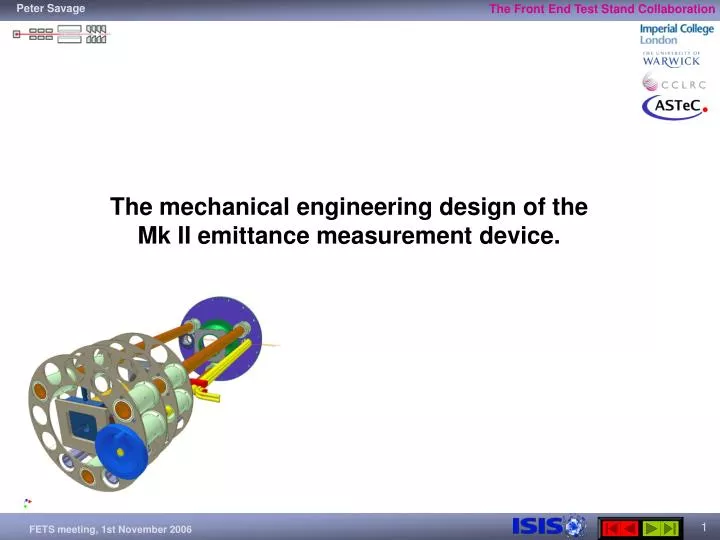
The mechanical engineering design of the Mk II emittance measurement device.
Mk I Emittance Scanner The ion source test facility vacuum tank Mounting flange Window Support rods Head Moving rod Camera _____________________________________________________________________ Isometric view of the Mk I emittance scanner that was designed to fit on the ion source test bench at the Rutherford Appleton Laboratory.
Mk I Emittance Scanner _____________________________________________________ The complete assembly mounted on the stainless steel flange.
Mk I Emittance Scanner – Head Design 10mm thick copper grid with a 25 x 25 array of 2mm diameter holes on a 3mm pitch. 0.3mm thick tungsten grid with 100 micron diameter holes Sliced view of the assembled head Scintillator Exploded view of the head assembly
Vacuum leak due to damage on sealing faces ___________________________________ Damage to the inner rod sealing ring, approx. 0.5mm wide and 0.5mm deep. ___________________________________ The rod has a scratch, approx. 05mm wide, 0.1mm deep, 30mm long.
Mk I Emittance Scanner – Conclusion Mk I was built and used successfully but also has experienced a few problems. It has been decided that we would benefit from a brand new emittance scanner with improvements made from what we have learned from the MkI. These improvements can be broadly split into three categories: 1) Stiffer support structure – apart from the obvious problems related to movement of the camera when mounted to a weak structure, I believe that the damage shown on the previous slide was due to the moving rod coming into contact with the main flange due to bending of the support structure. 2) Cooled head with a larger grid area – the MkI grid had 625 holes (25 x 25 array) on a 3mm pitch and hence covering 72mm square. This is less than the beam size. Also, damage appeared on the grid due to localised heating by the beam. While beam power is low there is no convection mechanism to cool the grids and so the MkII will have an active cooling system. 3) Improved vacuum seal – before the MkI became damaged the sealing onto the moving rod was working well but an improved vacuum design will be employed for the MkII that will also assist the cooling design.
The Mechanical Engineering Design of the Mk II emittance measurement device.
Mk II Emittance Scanner Bellows mount + window clamp Light port Handle to be replaced with stepper motor
Mk II Emittance Scanner – Head design Scintillator Grid Tungsten Grid Cooling Rods Moving Rod with keyway KF50 Flange Glidcop Grid (aluminium dispersion strengthened copper) End plates Copper grid cooling channel closing plate _____________________________________________________________________
Mk II Emittance Scanner – vacuum seal KF50 flange to be welded directly onto stainless steel flange KF50 flanges joined via bellows similar to those shown here from UHV Design _____________________________________________________________________ With this design there are no removable water joints exposed to vacuum and no moving parts sliding through vacuum seals as in the MkI design.
First Simple Model Beam power To investigate whether we need active cooling for the MkII emittance measurement device we can use FEA. First we will consider a copper block, being impacted by beam and being cooled by water. Copper block Model parameters: Beam Power = 36 W Material: Copper Block dimensions: L 100mm x W 100mm x H 100mm Cooling channel radius 10mm Ambient Temperature = 25C Cooling water temperature = 20C, forced convection Radiation ignored Cooling water
n1 e1 n2 e2 n3 e3 n4 First Simple Model The simple 1D model from figure 2 was then expanded to the 2D form as shown in figure 3 to better illustrate the effect of the beam power and the cooling. Figure 1. A simple model with symmetry Figure 2. A 2D model using PLANE55 elements Model parameters: Beam Power = 36 W Material: Copper Block dimensions: L 100mm x W 100mm x H 100mm Cooling channel radius 10mm Ambient Temperature = 25C Cooling water temperature = 20C, forced convection Radiation ignored The model as shown in figure 1 can be shown in it’s simplest form as in figure 2. This can be modelled using simple link elements and can also be solved using matrices and hence acts as a verification model. Figure 2. A 1D model with link elements.
Nodal temperatures After 1 minute: Tmax = 24.8°C Tmin = 23.6°C Nodal temperatures After 10 minutes: Tmax = 22.7°C Tmin = 21.8°C Nodal temperatures After 30 hours: Tmax = Tmin = 1198°C First Simple Model – cooled, radiation ignored Water cooled @ 20°C No cooling Water cooled @ 20°C Temperature change with time for nodes along the right hand edge (representing the centre of the 2D model). For a beam power of 36W, cooling water temperature of 20°C, initial temperatures of 25°C throughout (and convection coefficient of 3000W/m2.K). After about 6 minutes the block cooling reaches a thermal equilibrium with the beam power. With cooling switched off, after about 30 hours the OFC block will exceed the melting temperature of 1082°C.
Emittance Measurement Device – 36W for one hour Tmax = 22.2°C Tmin = 20.2°C Tmax = 60.0°C Tmin = 43.7°C Tmax = 37.0°C Tmin = 25.0°C No cooling Rod water cooling alone Grid water cooling alone Conclusion: A cooled rod or grid allows a thermal equilibrium to be reached. It is recommended that for either cooled solution a time of approx 2000 seconds / 30 minutes is allowed to elapse before taking data to let the grid stabilise.
Displacement due to heating - cooled grid Maximum displacement in X direction = 0.018mm Maximum displacement in Y direction = 0.041mm
THE RESULTS FROM THE THERMAL CALCULATIONS HAVE PROMPTED THE DEVELOPMENT OF A NEW DESIGN
Mk II Emittance Scanner – revised The combination of the tip / tilt stage with translation stages for X and Z and a custom translation adjustment for Y creates a system that is adjustable for all six degrees of freedom. Y Z X Improved camera mount Simplified cooling scheme Rod mounts optimised for strength versus size to allow for motor to be mounted close to the main flange Tip / tilt stage Translation stage
UHV Design _____________________________________________________________________ The search for a long travel edge welded vacuum bellows led me to this company called UHV design.
LSML64/35 700SD Linear Shift Mechanism _____________________________________________________________________ Side and end elevations of the LSML64 from UHV Design
Quote From UHV Design _____________________________________________________________________ UHV design will also be quoting for cooling using their support tube and for electrical feed-throughs for strain gauges.
New design with LSML _____________________________________________________________________ The new design showing just the bellows from the LSML.
Conclusions: • Purchasing the LSML from UHV Design will reduce the manufacturing effort and will provide a proven working system that will reduce ‘fine tuning’ time dramatically. • The cost of the LSML purchase may not prove to be significantly less than the cost to manufacture my design. • The remaining design work and manufacture for the main flange, the camera mount and grid + grid mount can proceed in parallel with the manufacture of the LSML.