Download
1 / 58
590 likes | 770 Vues
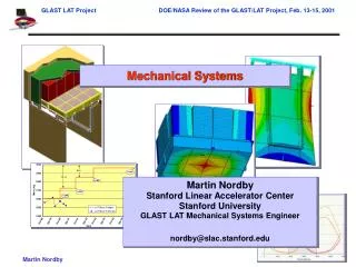
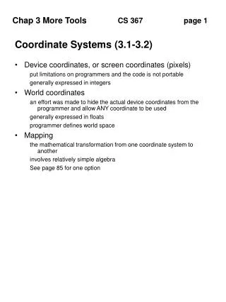
3 Mechanical systems 3.1 pose description and transformation 3.1.1 Description of coordinate system. Example 1. Preliminary. Robot Reference Frames World frame Joint frame Tool frame. T. P. W. R. O, O’. Coordinate Transformation Reference coordinate frame OXYZ

E N D
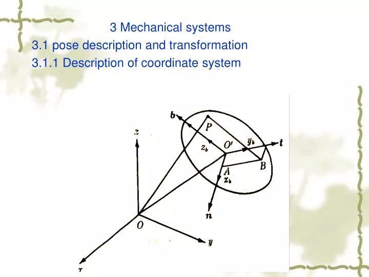
3 Mechanical systems 3.1 pose description and transformation 3.1.1 Description of coordinate system
Preliminary • Robot Reference Frames • World frame • Joint frame • Tool frame T P W R
O, O’ • Coordinate Transformation • Reference coordinate frame OXYZ • Body-attached frame O’uvw Point represented in OXYZ: Point represented in O’uvw: Two frames coincide ==>
Mutually perpendicular Unit vectors Properties: Dot Product Let and be arbitrary vectors in and be the angle from to , then Properties of orthonormal coordinate frame
Coordinate Transformation • Rotation only How to relate the coordinate in these two frames?
Basic Rotation • , , and represent the projections of onto OX, OY, OZ axes, respectively • Since
Basic Rotation Matrix • Rotation about x-axis with
Is it True? • Rotation about x axis with
Basic Rotation Matrices • Rotation about x-axis with • Rotation about y-axis with • Rotation about z-axis with
Basic Rotation Matrix • Obtain the coordinate of from the coordinate of Dot products are commutative! <== 3X3 identity matrix
Example 2 • A point is attached to a rotating frame, the frame rotates 60 degree about the OZ axis of the reference frame. Find the coordinates of the point relative to the reference frame after the rotation.
Composite Rotation Matrix • A sequence of finite rotations • matrix multiplications do not commute • rules: • if rotating coordinate O-U-V-W is rotating about principal axis of OXYZ frame, then Pre-multiply the previous (resultant) rotation matrix with an appropriate basic rotation matrix • if rotating coordinate OUVW is rotating about its own principal axes, then post-multiply the previous (resultant) rotation matrix with an appropriate basic rotation matrix
Coordinate Transformations • position vector of P in {B} is transformed to position vector of P in {A} • description of {B} as seen from an observer in {A} Rotation of {B} with respect to {A} Translation of the origin of {B} with respect to origin of {A}
Two Special Cases 1. Translation only • Axes of {B} and {A} are parallel 2. Rotation only • Origins of {B} and {A} are coincident
Homogeneous Representation • Coordinate transformation from {B} to {A} • Homogeneous transformation matrix Rotation matrix Position vector Scaling
Homogeneous Transformation • Special cases 1. Translation 2. Rotation
Example 3 • Rotation about the X-axis by
Homogeneous Transformation • Composite Homogeneous Transformation Matrix • Rules: • Transformation (rotation/translation) w.r.t (X,Y,Z) (OLD FRAME), using pre-multiplication • Transformation (rotation/translation) w.r.t (U,V,W) (NEW FRAME), using post-multiplication
Homogeneous Representation • A frame in space (Geometric Interpretation) (z’) (y’) (X’) Principal axis n w.r.t. the reference coordinate system
Homogeneous Transformation • Translation
? Composite Homogeneous Transformation Matrix Transformation matrix for adjacent coordinate frames Chain product of successive coordinate transformation matrices
Orientation Representation • Rotation matrix representation needs 9 elements to completely describe the orientation of a rotating rigid body. • Any easy way? Euler Angles Representation
Euler Angle I Euler Angle II Roll-Pitch-Yaw Sequence about OZ axis about OZ axis about OX axis of about OU axis about OV axis about OY axis Rotations about OW axis about OW axis about OZ axis • Euler Angles Representation ( , , ) • Many different types • Description of Euler angle representations
Euler Angle I, Animated w'= z w'"= w" f v'" v " v' y u'" u' =u" x
Euler Angle I Resultant eulerian rotation matrix:
Euler Angle II, Animated w'= z w" w"'= v"' v' =v" y u"' u" Note the opposite (clockwise) sense of the third rotation, f. u' x
Matrix with Euler Angle II Quiz: How to get this matrix ?
Z • Description of Roll Pitch Yaw Y X Quiz: How to get rotation matrix ?
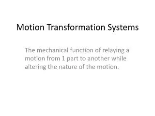
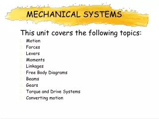
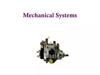
3.2 Transmission mechanisms Mechanisms are motion converters in that they transform motion from one form to some required form. Machine is a system that transmits or modifies the action of a force or torque to do useful work. (involving transmitting motion and force or torque) Kinematics is the term used for the study of motion without regard to forces.
3.2.1 kinematic chains Link is a part of a mechanism which has motion relative to some other part. Joint is the point of attachment to other link which allows the links attached to have relative movements among each other. Kinematic chain is a sequence of joints and links.
The slider-crank mechanism is an extremely cost-effective means of converting rotary to linear motion. The crank portion is the wheel that rotates about its center and has a rod of fixed lenght mounted to a point on its circumference; the other end of the connecting rod is attached to a linear stage which is constrained to move in only one dimension on a relatively frictionless surface.
At both its location the connecting rod is free to rotate thus the angle formed with the horizontal will change as a function of the disk’s position. As the disk travels from 0 to 180° in the counterclockwise direction, the linear stage moves a distance equal to 2r: if the disk continues to travle from 180° back to 0° - still in counterclockwise direction, the load will move in the opposite direction over exactly the same linear distance.
Cams – design criteria Law of motion for the follower: position, velocity, acceleration and jerk Machining problems: undercut Pressure angle
Gear Train Ratio The train ratio of a gear train is the ratio of the angular velocities of input and output members in the gear train. The train ratio here includes two factors, the magnitude and the relative rotating direction of the two members.
Advantages Gear mechanisms are widely used in variety fields. They can be used to transmit motion and power between two any spatial rotating shafts and there are many advantages for them, such as, big range power, high transmission efficiency, exact transmission ratio, long life and reliable performance etc . .
Harmonic Drive Harmonic Drive is a mechanical device for transmission of motion and power, which is based upon a unique principle of controlled elastic deformations of some thin-walled elements.
Components The three basic components of a Harmonic Drive are: wave generator, flexspline and circular spline. Any one of the three components may be fixed, while one of the remaining two may be the driver, and the other the driven, to effect speed increase or speed decrease and at fixed speed ratio. Or, two of the three components may be the driver while the third the driven so as to effect differential transmission.
Characteristc High reduction ratio with wide range High precision Small backlash large torque capacity High efficiency Small size and light weight Smooth running Low noise