Download
1 / 46
460 likes | 669 Vues
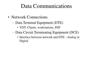
3. Data Communications. 3.1 Basic concepts of data communications and networking. Data Communications System. Transmitter – transmit data to another medium. Receiver – receive data from a transmitter. Medium of transfer – the medium for transfer of data. Medium. Microwave.

E N D
3. Data Communications 3.1 Basic concepts of data communications and networking
Data Communications System • Transmitter – transmit data to another medium. • Receiver – receive data from a transmitter. • Medium of transfer – the medium for transfer of data.
Medium Microwave Post Office Letter by post Transmitter Sender Receiver Recipient TV transmission station Antenna Data Communications System TV programme
Source System Destination System Source Transmitter Transmission system Receiver Destination Workstation Modem Public Telephone Network Modem Server Communications Model
Simplex Transmission • Simplex communication means that communication can only flow in one direction and never flow back the other way. Data
Half-duplex Transmission • Half-duplex data transmission means that data can be transmitted in both directions on a signal carrier, but not at the same time. Data
Full-duplex Transmission • Full-duplex data transmission means that data can be transmitted in both directions on a signal carrier at the same time. Data
Real life examples • Simplex transmission • Pager • Half-duplex transmission • Telephone, facsimile • Full-duplex transmission • Dual Carriageway
Data Transmission Rate • Data transmission rate: bps, Kbps, Mbps • bps – bits per second • Kbps – kilo-bits per second • Mbps – mega-bits per second • Bps – bytes per second • 1 Byte = 8 bits
Serial Transmission • The transfer of discrete signals one after another. • Bits travel sequentially along the same wire. • Send information over a single line one bit at a time, as in modem-to-modem connections.
Parallel Transmission • The simultaneous transmission of a group of bits over separate wires. • The transmission of 1 byte (8-bits) with computers.
Parallel Transmission • Relatively fast • Limited distance before data is lost • As short as possible (no longer than 15 feet) • As the length of cable increases so does the danger of cross-talk.
Serial Transmission • Not as fast as parallel transmission • Can transmit data for longer distances
Data bits Parity bit Start bit Stop bit The coding of a typical character sent in asynchronous transmission Asynchronous Transmission • In modem communication, a form of data transmission in which data is sent one character at a time. In addition, a parity bit is usually used for error checking. • Avoid timing problem by not sending long, uninterrupted streams of bits.
Idle state of line Odd, even, or unused Start bit 5 to 8 data bits 1 – 2 bit times 0 Stop 1 Remain idle or next start bit P bit Asynchronous Transmission Character format
Unpredictable time interval Between characters Start bit Stop bit Start bit Stop bit 1 1 1 1 0 0 0 1 0 0 1 0 1 1 0 0 Asynchronous Transmission 8-bit asynchronous character stream
Transmitter timing Start 0 100 200 300 400 500 600 700 800 1 2 3 4 5 6 7 8 Stop Receiver timing 0 93 186 279 372 465 558 651 744 Asynchronous Transmission Effect of timing error Assumptions: data rate of 10 kbps 0.1 ms each bit. The receiver is off by 7% or 0.007 ms per bit-time The receiver samples the incoming character every 0.093 ms (based on the transmitter’s clock).
Asynchronous Transmission • Advantages: • simple • cheap • Disadvantages: • requires an overhead of 2 – 3 bits per character (start and stop bits) (>=20%) • cannot send large blocks or bits between start and stop bits with great cumulative timing error
Synchronous Transmission • Data transfer in which information transmitted in block (frames) of bits separated by equal time intervals • A block of bits is transmitted in a steady stream without star and stop codes
Synchronous Transmission • Method 1: • Provide a separate clock line between transmitter and receiver • The other side uses these regular pulses as a clock • This technique works well over short distances • Method 2: • Embed the clocking information in the data signal
Synchronous frame format preamble 8-bit flag Control fields Control fields postamble 8-bit flag Data fields Synchronous Transmission
Synchronous Transmission • Advantage: • For sizable/large blocks of data, synchronous transmission is far more efficient that asynchronous. • The control information, preamble, and postamble are typically less than 100 bits. • E.g. 48 bits of control, preamble, and postamble with 1000-character block of data, each frame consists of 48 bits of overhead and 8000 bits of data, so % overhead = 48/8048 x 100% = 0.6%
Data Transfer Directed from PC to PC • Direct Cable Connection • A null modem cable allows you to connect your PC to another nearby PC or serial device using its modem protocol. • A null modem cable is limited to 30 feet in length. • A null modem cable is sometimes called crossover cable.
Crossover Cable • A crossover cable is a cable that is used to interconnect two computers by "crossing over" (reversing) their respective pin contacts. • Either an RS-232C or an registered jack (e.g. RJ-45) connection is possible.
RS-232C • Your computer modem uses one of your PC's serial connections or COM ports. • Serial communication between your PC and the modem and other serial devices adheres to the RS-232C (Recommended Standard-232 Current Version) standard.
1 2 3 4 5 6 7 8 9 10 11 12 13 14 15 16 17 18 19 20 21 22 23 24 25 RS-232C Pin Settings for Plug (Reverse Order for Socket) 25 pins
1 2 3 4 5 14 15 16 17 RS-232C Pin Settings for Plug (Reverse Order for Socket) 9 pins
RS-232C 1 – PG Protective ground 2 – TD Transmitted data (3 for 9-pin) 3 – RD Received data (2 for 9-pin) 4 – RTS Request to send (7 for 9-pin) 5 – CTS Clear to send (8 for 9-pin) 6 – DSR Data set ready (6 for 9-pin) 7 – SG Signal ground (5 for 9-pin) 8 – CD Carrier detect (1 for 9-pin) 9 – + voltage (testing) 10 – - voltage (testing) 11 – 12 – SCD Secondary CD 13 – SCS Secondary CTS
RS-232C 14 – STD Secondary TD 15 – TC Transmit clock 16 – SRD Secondary RD 17 – RC Receiver clock 18 – 19 – SRS Secondary RTS 20 – DTR Data terminal ready (4 for 9-pin) 21 – SQD Signal quality detector 22 – RI Ring indicator (9 for 9-pin) 23 – DRS Data rate select 24 – XTC External clock 25 –
Possible reasons to connect two computers directly to each other • Playing a game competitively (one person at each computer) with fast response time • Testing one computer by examining its behavior at the other computer • Saving the cost of a hub when you want to interconnect two devices in the same home or office
Data Modem Modem – Modulator and Demodulator Modulator – convert digital signal (data in PC) to analogue signal (data via telephone line) Demodulator – convert analogue signal to digital signal
Data Modem Modulation Digital signal Analogue signal PC Modem Public Telephone Network PC Modem Digital signal Analogue signal Demodulation
Data Modem • Baud Rate • This refers to the number of signals per one second transmitted • Bit Rate • The bit rate is multiplied by the bits per signal
Sources of errors during data transmission • Attenuation • Signal grows weak over distance • White noise • Caused by molecular movement • Impulse noise • Caused by electrical interference • Cross-talk • Caused by interference from adjacent lines
DCE and DTE • DTE • Data Terminal Equipment which is the ultimate source or final destination of data messages • DCE • Data Circuit-Terminating Equipment which connects the DTE to the communication circuits
HS The High Speed light indicates that your modem is currently operating at its highest available transmission rate AA The Auto Answer light indicates that your modem will automatically answer any incoming calls. This features allows access to your system while it is unattended CD The Carrier Detect light goes on when your modem has successfully made a connection with a remote computer OH The Off-Hook light goes on whenever your modem takes control of the phone line Abbreviations found in an External Modem
RD The Receive Data light flickers each time the modem receives data from the remote computer SD The Send Data light flashes whenever the modem sends data to the remote computer TR The Terminal Ready light goes on when the modem detects a DTR (Data Terminal Ready) signal from your communications software. This signal informs your modem that a communications program is loaded and ready to run MR The Modem Ready light lets you know that your modem is turned on and ready to operate Abbreviations found in an External Modem
Bandwidth • The capacity at which you can transfer data is called bandwidth • Typical telephone line: 33,600 kilobits per second (33.6 Kbps) • Cable TV: 10 megabits per second (10 Mbps) – almost 300 times the capacity of the normal phone connection
Bandwidth • Frequency • Frequency is measured in the number of cycles of change per second, or hertz (Hz). • Latency • In a network, latency, a synonym for delay, is an expression of how much time it takes for a packet of data to get from one designated point to another.
(wave length) Bandwidth f = 1 /
High frequency Bandwidth Wide bandwidth
Low frequency Bandwidth Narrow bandwidth
Bandwidth • Bandwidth is used to mean • How fast data flows on a given transmission path • The width of the range of frequencies that an electronic signal occupies on a given transmission medium • Any digital and analog signal has a bandwidth
Bandwidth • Voice-grade phone line • Range of freq.: 300 to 3000 Hz • Bandwidth = 3000 – 300 = 2700 • Human voice • Range of freq.: 20 to 20000 Hz • Bandwidth = 19980
E.g. Video transmission times Pixels per screen (640*480) 307200 Bytes per pixel 8 Total bits per screen 2457600 Frames per second 30 Total bits per second 73728000