Download
1 / 25
250 likes | 375 Vues
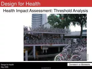
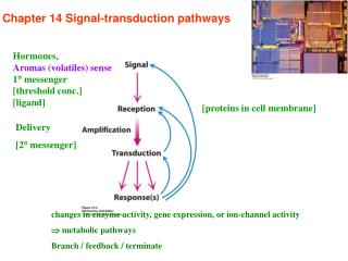
Brief Review of Vacuum Activity around the MKIs and “Safe” Threshold Values. M.J. Barnes Acknowledgements: Tobias Baer, Chiara Bracco , Laurent Ducimetière , Jan Uythoven. MKI8. 4 MKIs in RA87. MKI8D Exchanged TS3, 2012. MKI8C. MKI8B. MKI8A. Injected Beam. B1 bypass tube.

E N D
Brief Review of Vacuum Activity around the MKIsand “Safe” Threshold Values M.J. Barnes Acknowledgements: Tobias Baer, ChiaraBracco, Laurent Ducimetière, Jan Uythoven M.J. Barnes
MKI8 4 MKIs in RA87 MKI8D Exchanged TS3, 2012 MKI8C MKI8B MKI8A Injected Beam B1 bypass tube M.J. Barnes Ceramic tube & beam screen
Effect of MKI Pressure… • High instantaneous pressure in the kicker magnet tank, and near the capacitively coupled end of the beam screen, when pulsing the kickers, increases the probability of an electrical breakdown. SIS vacuum threshold for injection => 2.0e-9 mbar (temporarily increased to 2.5e-9 mbar, for 25 ns beam, during October 2011). • MKI SS & ACOND timing stopped for pressure > 5e-9 mbar (does not directly affect injection). • A prolonged pressure increases at the MKI, when pulsing the kickers, also increases the probability of an electrical breakdown. Occasional sparks at end of screen conductors, at bottom LHS. M.J. Barnes
POINT 2 (Clockwise Inj.): Vacuum & BLM Systems 3185.93m BLMQI.A5L2 & BLMQI.G5L2 BLMQI.04L2.B2I30_MQY 3169.79m BLMQI.05L2. B1E30_MQY 3177.70m BLMEI.05L2.B1E20_MKI.C5L2.B1 Anti-Ecloud solenoids installed on Q4 side, Q5 side and interconnects during TS 2010/2011 3174.32m BLMEI.05L2.B1E10_MKI.D5L2.B1 Interaction Point Distance: 3165.94m BLMQI.C5L2 3189.96m BLMQI.F4L2 3168.63m VGPB.G5L2.B 3170.20m VGPB.F5L2.B 3186.46m VGPB.I5L2.B 3187.39m VGPB.B5L2.B 3187.63m VGPB.A5L2.B 3181.97m VGP.C5L2.C 3183.96m VGP.A5L2.C 3179.99m VGP.B5L2.C 3174.16m VGPB.E5L2.B 3176.03m VGP.C5L2.C 3178.01m VGPB.D5L2.B 3172.06m VGP.D5L2.C 3185.66m 3177.74m 3182.25m 3173.77m 3178.29m 3170.56m VGP.78.5L2.C VGP.118.5L2.C VGP.158.5L2.C VGPB.59.5L2.B VGPB.98.5L2.B VGP.39.5L2.C VGPB.4.5L2.B VGPB.192.5L2.B VGPB.137.5L2.B BLM BLM VGP.176.5L2.C VGI.161.5L2.C VGI.121.5L2.C VGI.82.5L2.C VGI.42.5L2.C VGPB.194.5L2.B VGPB.2.5L2.B VGPB.625.4L2.B BLM BLM D MKI.D5L2.B1 C MKI.C5L2.B1 B MKI.B5L2.B1 BEAM 1 A MKI.A5L2.B1 Q5L2 side Capacitive Coupling (Double foot) Capacitive Coupling TMR (Single foot) TMR Capacitive Coupling TMR Capacitive Coupling TMR VGPB.195.5L2.R VGPB.192.5L2.R VGPB.176.5L2.R VGPB.137.5L2.R VGPB.97.5L2.R VGPB.57.5L2.R VGPB.4.5L2.R VGPB.2.5L2.R VGPB.625.4L2.R VIESA.193.5L2.C PS: VRPMB.25.5L2 3168.2m. Cct 6 VIESA.193.5L2.C PS: VRPMB.25.5L2 3187.2m. Cct 6 M.J. Barnes
Anti-Ecloud Solenoids at MKI, LSS2 Q4 Q5 MKI2D MKI2C MKI2B MKI2A Ecloud solenoid layout Courtesy of V. Baglin M.J. Barnes
MKI2. 25ns, 10/07/2012 VGPB.176.5L2.B C-D interconnect MKI2D B1: 6.5e13 max charge. Anti-elcoud solenoids @ 5A. Max pressure on B1 close to MKI2s: 1.9e-8mbar on VGPB.176.5L2.B (Q5 side of MKI2D). Pressure spikes during injection on both C-D interconnect and Q5 side of MKI2D: spike decays before next injection – no sparks of MKIs. M.J. Barnes
MKI2. 25ns, 24-25/10/2011 Switching solenoids off results in an increase in pressure x3, on Q5 side of MKI2D, and by a factor of ~2 in MKI2D. VGPB.176.5L2.B pressure spikes Ecloud solenoids off C-D interconnect MKI2D B1: 1.9e14 max charge. Anti-elcoud solenoids switched between 0A, 3A and 5A. Max pressure on B1 close to MKI2s: 1.7e-7mbar on VGPB.176.5L2.B (Q5 side of MKI2D): this pressure IS sensitive to Ecloudsolenoid state (ON or OFF)….. M.J. Barnes
POINT 8 (Anticlockwise Inj.): Vacuum & BLM Systems 23477.63m BLMQI.05R8.B2E30_MQY 23469.8m BLMEI.05R8.B2E20_MKI.C5R8.B2 Interaction Point 23460.82m BLMQI.04R8.B1I30_MQY 23478.8m BTVSI.C5R8.B2 (BTVSI084) 23479.12m to 23479.20m VVGST.I5R8.R 23460.11m to 23460.19m VVGST.A5R8.R Anti-Ecloud solenoids installed: on Q4 side and Q5 side during TS 2010/2011; B-C and C-D interconnects 6/07/2011 A-B interconnects?? (after 22/09/2011) 23481.60m BLMQI.C5R8 23473.34m BLMEI.05R8.B2E10_MKI.D5R8.B2 Distance: 23457.68m BLMQI.F4R8 23462.00m BLMI.5R8.B2 23473.63m VGPB.F5R8.R 23471.63m VGP.C5R8.C 23461.2m VGPB.C5R8.R 23465.70m VGPB.D5R8.R 23469.66m VGPB.E5R8.R 23479.04m VGPB.H5R8.R 23463.71m VGP.A5R8.C 23467.67m VGP.B5R8.C 23475.60m VGP.D5R8.C 23477.46m VGPB.G5R8.R 23465.41m 23465.96m 23469.93m 23473.89m 23477.31m VGPB.4.5R8.R VGP.39.5R8.C VGP.78.5R8.C VGP.118.5R8.C VGPB.59.5R8.R VGPB.138.5R8.R VGPB.98.5R8.R VGP.158.5R8.C VGPB.176.5R8.R BLM BLM VGPB.2.5R8.R VGPB.14.5R8.R VGI.36.5R8.C VGI.75.5R8.C VGI.115.5R8.C VGI.155.5R8.C VGPB.195.5R8.R VGPB.2.6R8.R BLM BLM BLM A MKI.A5R8.B2 B MKI.B5R8.B2 C MKI.C5R8.B2 D MKI.D5R8.B2 BEAM 2 Q4R8 side Q5R8 side Capacitive Coupling Capacitive Coupling Capacitive Coupling Capacitive Coupling (Double foot) TMR TMR TMR (Single foot) TMR VGPB.2.5R8.B VIESA.3.5R8.C PS: VRPMB.21.5R8 23459.8m. Cct 12 VGPB.4.5R8.B VGPB.60.5R8.B VGPB.99.5R8.B VGPB.139.5R8.B VGPB.192.5R8.B VGPB.195.5R8.B VGPB.2.6R8.B VIESA.193.5R8.C PS: VRPMB.21.5R8 23478.8m. Cct 12 M.J. Barnes
Anti-Ecloud Solenoids at MKI, LSS8 Q5 Q4 MKI8A MKI8B MKI8C MKI8D Ecloud solenoid layout Courtesy of V. Baglin M.J. Barnes
MKI8. 50ns, 24/09/2012 Spark Solenoid: 5A B1 intensity C-D interconnect VGPB.192.5R8.R (SoftStart): B1 circulating VGPB.192.5R8.R Solenoid: 3A B1: 4e13 max charge. Anti-elcoud solenoids initially at 3A. No precursor to breakdown of MKI8D: breakdown at Q5 end (beam screen suspected) … Relatively high pressure close to MKI8s when B1 injected. When solenoid current was increased from 3A to 5A large reduction in pressure in C-D interconnect and thus in MKI8C and MKI8D: increases SIS interlock level for MKI8 solenoids. Significant vacuum activity on VGPB.192.5R8.R during subsequent MKI8 SoftStart. M.J. Barnes
MKI8. 25ns, 10/07/2012 Ecloud solenoid (5A) VGPB.192.5R8.R C-D interconnect MKI8D B2: 2.7e13 max charge. Anti-elcoud solenoids @ 5A. Max pressure on B2 close to MKI8s: 2.4e-8mbar on VGP.192B.5R8.R (Q5 side of MKI8D). Pressures rise during injection on both Q5 side of MKI8D and C-D interconnect: pressure decays (rapidly) before next injection – no spark. M.J. Barnes
MKI8. UFO MD – 50ns. 22/06/2012 Solenoids on interconnects Solenoids by Q4 & Q5 2 Interconnect solenoids OFF Pressure rise in MKI8C-D interconnect 1 Q4 & Q5 solenoids OFF Pressure rise on Q5 side of MKI8D Q5 side of MKI8D MKI8C spark MKI8D MKI8C After switching off interconnect solenoids, pressure in C-D interconnect increases by a factor of ~70 !! Solenoids of Q4 & Q5 also effect MKI8D (and MKI8C) pressure. Spark in MKI8C (probably at end of beam screen) after 11 pulses – [MD pulsing MKIs in beam gap]. To minimize probability of beam screen spark, interlock injection on pressure of (kicked beam?) interconnects – e.g. SIS threshold of 5e-9 mbar. M.J. Barnes
MKI8. 25ns, 24/10/2011 VGPB.192.5R8.R Switching solenoids off results in an increase in pressure, on C-D interconnect, and thus MKI8D by factor of ~3. C-D interconnect MKI8D B2: 9e13 max charge. Anti-elcoud solenoids switched between 0A and 5A. Max pressure on B2 close to MKI8s: 6e-8mbar on VGPB.192.5R8.R (Q5 side of MKI8D). Pressure on VGPB.192.5R8.R not sensitive to Ecloudsolenoid current (in this case)….. Pressure in C-D interconnect, and thus magnet, is sensitive to Ecloud solenoid being on or off. Max. pressure during injection ~6e-9, with several injections > 4e-9 mbar. M.J. Barnes
MKI Vacuum Integral - 2011 • MKI8-D sparked on: • April 17, 2011: @51.3kV and 7800ns – following a period of “high” pressure (50ns beam); • Oct. 25, 2011: @54.3kV and 1200ns (SS) – following a period of pressure of ~9e-9mbar (25ns beam, Anti-ecloud solenoids off). 5x10⁻⁷ 1x10⁻⁸ 1x10⁻⁸ 5x10⁻⁷ 8 Feb 2011 to 18 Apr 2011 (Spark on 17/04) Pressure.Time Integral: MKI8D: 4.7*10^-7 mbar.hours 1 Sept 2011 to 26 Oct 2011 (Spark on 25/10) Pressure.Time Integral: MKI8D: 2.9*10^-7 mbar.hours 4x10⁻⁸ 1.2x10⁻⁶ 4x10⁻⁸ 1.2x10⁻⁶ 1 Sept 2011 to 26 Oct 2011 (Spark on 25/10) Pressure.Time Integral: C-D interconnect: 0.7*10^-6 mbar.hours March April Oct. 8 Feb 2011 to 18 Apr 2011 (Spark on 17/04) Pressure.Time Integral: C-D interconnect: 1.1*10^-6 mbar.hours M.J. Barnes
MKI Vacuum Integrals - 2012 • MKI8-D sparked on: • April 9, 2012: @51.3kV and 7800ns – following a period of “high” pressure (50ns beam); • Apr. 15, 2012: @51.3kV and 7800ns (SS). MKI8D: 13/03/2012 to 15/04/2012 M.J. Barnes
MKI Pressure → Sublimation Extended periods of raised pressure de-conditions the MKI magnets; Vacuum-Integral thresholds are set for each tank, based on experience; With an extended period of high pressure, the vacuum integral can relatively quickly reach its threshold (e.g. 2.88e-7mbar.hours/9e-9mbar => 32 hours, or 4.7e-7/14e-9 => 34 hours); MKIs are generally sublimated, to restore good vacuum, at each TS. The vacuum integrals are then RESET to zero; Access is required to sublimate the MKIs. Sublimation of MKI2 – Sept. 2012. M.J. Barnes
Conclusions • High instantaneous pressure in the kicker magnet tank, and near the capacitively coupled end of the beam screen, when pulsing the kickers, increases the probability of an electrical breakdown. • SIS interlocks prevents injection with “high” (>2e-9 mbar) instantaneous pressure in an MKI tank; • SIS interlock will be implemented for “high” (>5e-9 mbar?) instantaneous pressure in the beam-pipes immediately around the MKIs. This must be implemented before the 25ns ns scrubbing run….. Pressure threshold will be adjusted based on experience. • A prolonged pressure increases at the MKI, when pulsing the kickers, also increases the probability of an electrical breakdown. The pressure in the MKI tanks is presently integrated w.r.t. time and SIS interlock thresholds are defined for each integral. • If the integral exceeds the SIS threshold a sublimation should be carried out.. Hence, to minimize de-conditioning of the MKIs and the need for a sublimation, it is strongly recommended that the MKI anti-ecloud solenoids are kept on throughout both normal operation and, in general, during MDs. • Anti-ecloud solenoids around MKIs, and even those close to Q4 & Q5, significantly effect pressure in MKI interconnects and MKIs. • SIS interlock prevents injection if current of solenoids, around MKIs, < threshold. • Ecloud suppression in MKI8C-D interconnect presently requires > 3A (previously 3A was OK). • Have MKI Ecloud solenoids (and maybe those next to Q4 & Q5) ON during the 25ns scrubbing run: • ‘probe’ the effect of changing the coil current; • avoid pushing up the vacuum integral too much. M.J. Barnes
Spare Slides …. M.J. Barnes
MKI8. 50ns, 24/09/2012 Solenoid: 5A Spark B1 intensity VGPB.192.5R8.R (SoftStart): B1 circulating VGPB.192.5R8.R (SoftStart) VGPB.192.5R8.R (SoftStart) C-D interconnect Solenoid: 3A B2 intensity VGPB.192.5R8.R During MKI8 SoftStart, following breakdown of MKI8D, considerable vacuum activity seen on VGPB.192.5R8.R: vacuum activity reduces for subsequent SoftStarts….. M.J. Barnes
MKI8D Waveforms During Spark – 24/09/2012 MS Conclusion: given a cable delay of ~125ns between MS and magnet input, breakdown is close to pulse (and injected beam) entrance of MKI8D. TMR ~800ns ~550ns M.J. Barnes
MKI8. 450 GeV. 1200 bunches. 19 May 2011. 9.7e-10mbar 9.2e-10mbar 5A 5A 5A 3A 3.9e-10mbar 3.4e-10mbar 3.9e-10mbar 2.5e-10mbar 3.1e-10mbar 2.5e-10mbar 1.5e-10mbar 0A Switching off Ecloud solenoid current results in an exponential increase in A5R8 & D5R8 pressure. Switching Ecloud solenoid current on results in an exponential decrease in A5R8 & D5R8 pressure. M.J. Barnes
MKI2. 450 GeV. 19 May 2011. 9e-10mbar ~9e-10mbar 6A 1200 bunches 5A 1020 bunches 5A 4.3e-10mbar 3.8e-10mbar 3.6e-10mbar 3.5e-10mbar 3.1e-10mbar 2A 3.7e-10mbar 1.9e-10mbar 1.9e-10mbar 1.9e-10mbar 1.8e-10mbar 1.7e-10mbar 0A Reducing Ecloud solenoid current from 5A to 2A increases A5L2 & D5L2 pressure by ~10%. Switching off Ecloud solenoid current results in an exponential increase in A5L2 & D5L2 pressure. Switching Ecloud solenoid current on results in an exponential decrease in A5L2 & D5L2 pressure. M.J. Barnes
MKI2. 450 GeV. 19 May 2011. ‘2.5L2’: 4.9e-8 mbar 6A ‘192.5L2’: 4.9e-8 mbar 1200 bunches ‘4.5L2’: 4.6e-8 mbar 5A ‘mag. A’: 9e-10mbar ‘4.5L2’: 1.7e-8 mbar ‘4.5L2’: 1.6e-8 mbar 2A ‘4.5L2’: 1.5e-8 mbar ‘2.5L2’: 1.1e-8 mbar ‘192.5L2’: 1.1e-8 mbar ‘192.5L2’: 1.1e-8 mbar ‘2.5L2’: 1.0e-8 mbar ‘2.5L2’: 9.0e-9 mbar ‘mag. A’: 3.6e-10mbar 0A Switching off Ecloud solenoid current results in an exponential increase in ‘2.5L2’, ‘4.5L2’, and ‘192.5L2’, pressure by a factor of between 3 & 5. Switching Ecloud solenoid current on results in an exponential decrease in ‘2.5L2’, ‘4.5L2’, and ‘192.5L2’, pressure by a factor of between 3 & 5. NOTEs: Labelled pressure gauges, outside of kickers, have “yellow fill” on previous slide (no reading from ‘176.5L2’); Note maximum scale for kicker magnets (5e-9mbar) and near to 4L2 & 5L2 (5e-8 mbar). M.J. Barnes
LHC Injection Kicker: Maximum Temperatures During Oct. 2011 • Magnet PT100’s are mounted on ground plates: these plates contact the ground busbar and magnet capacitors; • Ground busbar does not contact ferrites – hence heat conduction to magnet PT100’s is mainly via magnet capacitors. Hence Mag_Up would be expected to measure a higher temperature than Mag_Dn, but …. • Tube_Up temperature > Tube_Dn temperature, maybe because of more cooling at “Dn” end (due to SS tube and “cage” around ferrites??). • The Power (W/m) shown is derived from impedance measurements – measured magnet temperature does not correlate with the power…. Screen conductors capacitively coupled to “ground” (metallization on ceramic tube) NO Capacitor here Screen conductors soldered to “ground” (Ferrites mounted on SS tube) PT100 Tube_Up HV plate ground plate HV plate ground plate ferrite yoke capacitor PT100 Tube_Dn Kicked Beam PT100 Mag_Up PT100 Mag_Dn Beam impedance reduction ferrites (lossy + low-loss) Beam impedance reduction ferrite (lossy + low-loss) TMR connection entrance box connection M.J. Barnes: LMC
MKI8: 6 July 2011 Anti-Ecloud solenoids on C-D interconnect Q5 side of MKI8s As per Christmas 2011-2012 TS: anti-Ecloud solenoids installed on all MKI interconnects and adjacent to Q4 & Q5. M.J. Barnes: LMC