Download
1 / 41
460 likes | 856 Vues
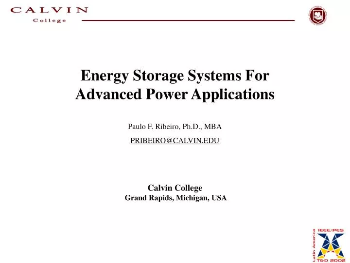
Energy Storage Systems For Advanced Power Applications Paulo F. Ribeiro, Ph.D., MBA PRIBEIRO@CALVIN.EDU Calvin College Grand Rapids, Michigan, USA. Energy Storage Energy is a Life Sustainable Business Sustainability Efficiency Performance Conservation Renewable Sources

E N D
Energy Storage Systems For Advanced Power Applications Paulo F. Ribeiro, Ph.D., MBA PRIBEIRO@CALVIN.EDU Calvin College Grand Rapids, Michigan, USA
Energy Storage • Energy is a Life Sustainable Business • Sustainability • Efficiency • Performance • Conservation • Renewable Sources • Present socio-economic realities – limits developments • Better Understanding of Performance Issues is Needed
Abstract • Energy storage technologies do not represent energy sources • Provide valuable added benefits to improve: • stability, power quality and security of supply. • Battery Technologies • Flywheel Technologies • Advanced / Super Capacitors • Superconducting Energy Storage Systems
Introduction • Electric Power Systems - Experiencing Dramatic Changes • Electric load growth and higher regional power transfers in a largely interconnected network: >>complex and less secure power system operation. • Power generation and transmission facilities - unable to meet these new demands • Growth of electronic loads has made the quality of power supply a critical issue. • Power system engineers facing these challenges - operate the system in more a flexible. • In face of disturbances - generators unable to keep the system stable. • High speed reactive power control is possible through the use of flexible ac transmission systems (FACTS) devices. • Better solution: rapidly vary real power without impacting the system through power circulation. • Recent developments and advances in energy storage and power electronics technologies
Energy Storage Systems for Advanced Transmission and Distribution Applications • Energy Storage Technology – Power Convert • Factors: • The amount of energy that can be stored in the device. • The rate at which energy can be transferred into or out of the storage device. • Power/Energy ranges for near to mid-term technology have projected • Integration of energy storage technologies with Flexible AC Transmission Systems (FACTS) and custom power devices are among the possible advanced power applications utilizing energy storage.
Power vs. Energy Ranges for Near to Midterm Technology SMES 100 10 Power (MW) Flywheel Batteries Capacitor 1 1 10 100 1000 Energy (MWsec) Benefits: transmission enhancement, power oscillation damping, dynamic voltage stability, tie line control, short-term spinning reserve, load leveling, under-frequency load shedding reduction, circuit break reclosing, sub-synchronous resonance damping, and power quality improvement.
A. Superconducting Magnetic Energy Storage (SMES) Solenoid Configuration (100 MJ – 4kA - 96MW System)
A. Superconducting Magnetic Energy Storage (SMES) • SMES’ efficiency and fast response capability (MW/millisecond) have been, and can be further exploited in applications at all levels of electric power systems. Potential applications have been studied since 1970’s. • load leveling, • frequency support (spinning reserve) during loss of generation, • enhancing transient and dynamic stability, • dynamic voltage support (VAR compensation), • improving power quality, • increasing transmission line capacity, thus enhancing overall security and reliability of power systems. • Further development continues in power conversion systems and control schemes, evaluation of design and cost factors, and analyses for various SMES system applications.. [iii] D. Lieurance, F. Kimball, C. Rix, C. Luongo,”Design and Cost Studies for Small Scale Superconducting Magnetic Energy Storage Systems,”IEEE Transactions on Applied Superconductivity, vol. 5, no. 2, June 1995, pp. 350-353. S.M. Schoenung, W.R. Meier, R. L. Fagaly, M. Heiberger, R.B. Stephens, J.A. Leuer, R.A. Guzman,”Design, Performance, and Cost Characteristics of High Temperature Superconducting Magnetic Energy Storage,”IEEE Transactions on Energy Conversion, vol. 8, no. 1, March 1993, pp. 33-38.
A. Superconducting Magnetic Energy Storage (SMES) Energy-power characteristics for potential SMES applications for generation, transmission, and distribution.
Photo Source: UP Networks B. Battery Energy Storage Systems (BESS) Batteries are one of the most cost-effective energy storage technologies available, with energy stored electrochemically. Key factors in battery for storage applications include: high energy density, high energy capability, round trip efficiency, cycling capability, life span, and initial cost. Battery technologies under consideration for large-scale energy storage. Lead-acid batteries can be designed for bulk energy storage or for rapid charge/discharge. Mobile applications are favoring sealed lead-acid battery technologies for safety and ease of maintenance. Valve regulated lead-acid (VRLA) batteries have better cost and performance characteristics for stationary applications.
BESS Example – Transmission/Distribution Application Lead-acid batteries, have been used in a few commercial and large-scale energy management applications. The largest one is a 40 MWh system in Chino, California, built in 1988. The table below lists and compares the lead-acid storage systems that are larger than 1MWh.
= q CV e A = C d 1 = 2 E CV 2 dt = * + * dV i i R tot C tot C. Advanced / Super / Capacitors • The amount of energy a capacitor is capable of storing can be increased by either increasing the capacitance or the voltage stored on the capacitor. • The stored voltage is limited by the voltage withstand strength of the dielectric. • As with batteries, the turn around efficiency when charging/discharging capacitors is also an important consideration, as is response time. • The effective series resistance of the capacitor has a significant impact on both. The total voltage change when charging or discharging capacitors is shown in equation
C. Advanced / Super / Capacitors NESSCAP 10F/2.3V
C. Advanced Capacitors Advantages Disadvantage Power (higher density) Energy Density Energy Efficiency (higher) Maintenance Discharge Parameters Electrostatic Cap Ultra-Cap Battery Discharge 10E-3-6 sec 1-30 sec 0.3-3 hours Charge 10E-3-6 sec 1-30 sec 1-5 hours Energy Density <0.1 Wh/kg 1-10Wh/kg 20-100Wh/kg Power Density >10E4Wh/kg 10-20E4Wh/kg 5-200Wh/kg Charge Eff. ~1.0 0.9-0.95 0.7-0.85 Cycle life infinite >500,000 500-2000 Ness Caps
Active Power, Inc. D. Flywheel Energy Storage (FES) Flywheels can be used to store energy for power systems when the flywheel is coupled to an electric machine. Stored energy depends on the moment of inertia of the rotor and the square of the rotational velocity of the flywheel.. Energy is transferred to the flywheel when the machine operates as a motor (the flywheel accelerates), charging the energy storage device. The flywheel is discharged when the electric machine regenerates through the drive (slowing the flywheel). 1 2 E = I The moment of inertia (I) depends on the radius, mass, and height (length) of the rotor 2 The energy storage capability of flywheels can be improved either by increasing the moment of inertia of the flywheel or by turning it at higher rotational velocities, or both.
D. Flywheel Energy Storage (FES) Flywheel energy storage coupled to a dynamic voltage restorer.
Manufacturer Technology Capacity (kW) Capacity (time) A Flywheel 120 kW 20 sec B Flywheel/Battery 160 kW 15-30 min C Battery 3.1 - 7.5 kVA 15 min Battery 0.7 - 2.1 kVA 10 min Battery 700 - 2100 kVA 13 min Battery 7.5 - 25 kVA 17 min D Battery 1250 kVA 15 min Flywheel 700 kW 10 min E Battery 450 - 1600 kVA 6-12 min F Flywheel/Battery 5-1000 kVA 5-60 min G Battery 0.14 - 1.2 kVA 5-59 min H Battery 0.28 - 0.675 kVA 15 min Example – End-User Application Energy Storage / UPS Systems Source: EPRI
Performance \ ESS SMES BESS FES Advanced capacitor Dynamic Stability Needs to be explored Transient Stability Voltage Support Area Control/ Frequency Regulation Transmission Capability Improvement Power Quality Improvement Advanced Power Systems Applications SMES can inject and absorb power rapidly, but battery and flywheel systems are modular and more cost effective. Advanced flywheels and advanced capacitor technologies are still being developed and are emerging as promising storage technologies as well.
A. Integration of Energy Storage Systems into FACTS Devices FACTS controllers are power electronics based devices that can rapidly influence the transmission system parameters such as impedance, voltage, and phase to provide fast control of transmission or distribution system behavior. FACTS controllers that can benefit the most from energy storage are those that utilize a voltage source converter interface to the power system with a capacitor on a dc bus. This class of FACTS controllers can be connected to the transmission system in parallel (STATCOM), series (SSSC) or combined (UPFC) form, and they can utilize or redirect the available power and energy from the ac system. Without energy storage, FACTS devices are limited in the degree of freedom and sustained action
A. Integration of Energy Storage Systems into FACTS Devices Steady State Issues Voltage Limits Thermal Limits Angular Stability Limits Loop Flows Dynamic Issues Transient Stability Damping Power Swings Post-Contingency Voltage Control Voltage Stability Subsynchronous Res. Traditional Solutions Breaking Resistors Load Shedding Advanced Solutions FACTS Energy Storage Fixed Compensation Transmission Link Enhanced Power Transfer and Stability Line Reconfiguration Better Protection SVC STATCOM TCSC, SSSC UPFC FACTS Devices Increased Inertia
A. Integration of Energy Storage Systems Energy Storage for Generation Transmission Distribution End-User Functions Transmission Cap. Reliability Stability Continuity Reliability Power Quality Power Quality Spinning Reserve Load Leveling Configurations Shunt Comp. Shunt / Series Comp. Shunt / Series Comp. Shunt Comp. Applications FACTS Devices Statcom PQ Parks Arc Furnace
STATCOM with SMES The performance of a power-electronics -energy-storage-enhanced device is very sensitive to the location with regard to generation and loads, topology of the supply system, and configuration and combination of the compensation device. STATCOM/SMES dynamic response to ac system oscillations
No Compensation 60.8 System Frequency (Hz) 59.2 time (sec) 1 STATCOM + SMES 2 STATCOMs 60.8 60.8 System Frequency (Hz) System Frequency (Hz) 59.2 59.2 time (sec) time (sec) Enhanced Voltage and Stability Control Voltage and Stability Control ( 80 MVA Inverter + 100Mjs SMES) (2 x 80 MVA Inverters) STATCOM with SMES Location and Configuration Type Sensitivity
FACTS with BESS (b) reactive power from 755Var to 355Var (a) active power from 50W to 400 W Predicted and experimental response of the SSSC/BESS
(a) STATCOM vs STATCOM/BESS (b) SSSC vs SSSC/BESS (c) STATCOM/BESS vs SSSC/BESS vs UPFC FACTS with BESS Active power flow between areas
(a) STATCOM vs STATCOM/BESS (b) SSSC vs SSSC/BESS (c) STATCOM/BESS vs SSSC/BESS vs UPFC FACTS with BESS Voltage at Area 2 bus
B. Advanced HVDC Transmission and Distribution Improvements in power electronic device technologies have led to significant improvements in the flexibility of dc transmission systems through the ability to use voltage source converters. Traditional direct current systems see limited use as high power, high voltage dc (HVdc) transmission systems. Advanced dc systems allows lower voltage dc transmission system capable of supporting a large number of standard “off the shelf” inverters. Energy storage can be added to the dc system, providing improved response to fast load changes drawn by the inverters. DC system with capacitive energy storage added to the dc system through a dc to dc converter.
C. Power Quality Enhancement with Energy Storage Custom power devices address problems found at distribution level, such as voltage sags, voltage swells, voltage transients and momentary interruptions. The most common approaches to mitigate these problems focus on customer side solutions such as Uninterruptible Power Supply (UPS) systems based on battery energy storage. Alternative UPS systems based on SMES and FESS are also available. Dynamic voltage restorer (DVR) with capacitor storage
Q FACTS + Energy Storage The Role of Energy Storage: real power compensation can increase operating control and reduce capital costs STATCOM Reactive Power Only Operates in the vertical axis only P MVA Reduction P - Active Power Q - Reactive Power The Combination or Real and Reactive Power will typically reduce the Rating of the Power Electronics front end interface. Real Power takes care of power oscillation, whereas reactive power controls voltage. STATCOM + SMES Real and Reactive Power Operates anywhere within the PQ Plane / Circle (4-Quadrant)
Power Electronics - Semiconductor Devices Decision-Making Matrix
Universal Topology + Energy Storage Implementation E2 / 2 P&Q E1 / 1 I X Regulating Bus Voltage + Injected Voltage + Energy Storage Can Control Power Flow Continuously, and Support Operation Under Severe Fault Conditions (enhanced performance) Plus Energy Storage
Cost Considerations • Energy storage system costs for a transmission application are driven by the operational requirements. • The costs of the system can be broken into three main components: • The energy storage system, • The supporting systems (refrigeration for SMES is a big item) and • The Power Conversion System. • The cost of the energy storage system is primarily determined by the amount of energy to be stored. The configuration and the size of the power conversion system may become a dominant component for the high-power low-energy storage applications. For the utility applications under consideration, estimates are in the range of $10-100K per MJ for the storage system.
Cost Considerations In order to establish a realistic cost estimate, the following steps are suggested: · identify the system issue(s) to be addressed; · select preliminary system characteristics: · define basic energy storage, power, voltage and current requirements; · model system performance in response to system demands to establish effectiveness of the device; · optimize system specification and determine system cost; · determine utility financial benefits from operation; · compare system’s cost and utility financial benefits to determine adequacy of utility’s return on investment, · compare different energy storage systems performance and costs
$ I $$$ $ I additional cost savings possible Technology & Cost Trends
Conclusions • Potential performance benefits produced by advanced energy storage applications: • improved system reliability • dynamic stability • enhanced power quality • transmission capacity enhancement • area protection, etc.. • FACTS (Flexible AC Transmission Systems) devices which handle both real and reactive power to achieve improved transmission system performance are multi-MW proven electronic devices now being introduced in the utility industry. In this environment, energy storage is a logical addition to the expanding family of FACTS devices.
Conclusions • As deregulation takes place, generation and transmission resources will be utilized at higher efficiency rates leading to tighter and moment-by-moment control of the spare capacities. • Energy storage devices can facilitate this process, allowing the utility maximum utilization of utility resources. • The new power electronics controller devices will enable increased utilization of transmission and distribution systems with increased reliability. • This increased reliance will result in increased investment in devices that make this asset more productive. • Energy storage technology fits very well within the new environment by enhancing the potential application of FACTS, Custom Power and Power Quality devices.