Download
1 / 15
150 likes | 212 Vues
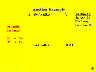
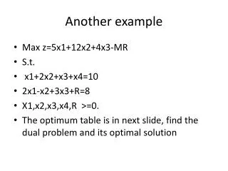
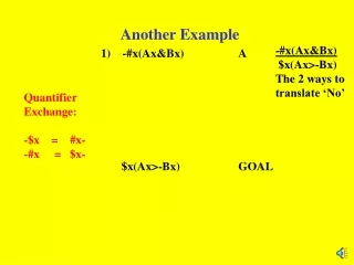
Another Example. Another Example. oCYL=0. /iSENSOR •iRET. S0. iSENSOR. S2. oCYL=0. S1. iEXT. oCYL=1. Another Example. oCYL=0. /iSENSOR •iRET. S0. iSENSOR. S2. oCYL=0. S1. iEXT. oCYL=1. Example #2 State Diagram. CurrSt iSENSOR iEXT iRET | NextSt

E N D
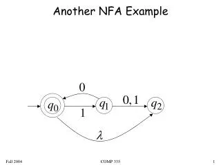
oCYL=0 /iSENSOR•iRET S0 iSENSOR S2 oCYL=0 S1 iEXT oCYL=1 Another Example
oCYL=0 /iSENSOR•iRET S0 iSENSOR S2 oCYL=0 S1 iEXT oCYL=1 Example #2 State Diagram CurrSt iSENSOR iEXT iRET | NextSt ------------------------------------ S0 0 X X | S0 S0 1 X X | S1 S1 X 0 X | S1 S1 X 1 X | S2 S2 0 X 0 | S2 S2 0 X 1 | S0 S2 1 X X | S2
oCYL=0 /iSENSOR•iRET S0 iSENSOR S2 oCYL=0 S1 iEXT oCYL=1 Example #2 State Diagram CurrSt iSENSOR iEXT iRET | NextSt ------------------------------------ S0 0 X X | S0 S0 1 X X | S1 S1 X 0 X | S1 S1 X 1 X | S2 S2 0 X 0 | S2 S2 0 X 1 | S0 S2 1 X X | S2 cS0 = cS2•/iSENSOR•iRET + cS0•/iSENSOR + /cS0•/cS1•/cS2 cS1 = cS0•iSENSOR + cS1•/iEXT cS2 = cS1•iEXT + cS2•/(/iSENSOR•iRET) = cS1•iEXT + cS2•(iSENSOR + /iRET)
State Machines in Ladder Logic • Pure relay logic - traditional design: • 2 states = 1 coil • 3-4 states = 2 coils • 5-8 states = 3 coils, etc. • difficult to debug, modify and document • Pure relay logic - “one-hot” design • 1 coil per state • easier to debug, modify, and document • watch out for “illegal” states • RLL-Plus • “Stages” • JMP “coils” • easiest to write and maintain • not available in all brands of PLC’s
oCYL=0 /iSENSOR•iRET S0 iSENSOR S2 oCYL=0 S1 iEXT oCYL=1 Example #2 State Diagram cS0 = cS2•/iSENSOR•iRET + cS0•/iSENSOR + /cS0•/cS1•/cS2 cS1 = cS0•iSENSOR + cS1•/iEXT cS2 = cS1•iEXT + cS2•iSENSOR + cS2•/iRET)
oCYL=0 /iSENSOR•iRET S0 iSENSOR S2 oCYL=0 S1 iEXT oCYL=1 Ex #2 - RLL-Plus Stages
Multi-state Example • When sensor detects block; clamp block, drill hole, shift, drill 2nd hole, shift back, release clamp
iSENSOR block present iDRILLDN drill is down iDRILLUP drill is up iCLAMPED fully clamped iRELEASED fully unclamped iPOS1 unshifted iPOS2 shifted oDRILL start drilling oCLAMP activate clamp oSHIFT shift block holder Inputs and Outputs
State Diagrams • One state per “action” • Look for “wait” states needed